Difference between revisions of "Subwoofer"
| Line 95: | Line 95: | ||
|- | |- | ||
|} | |} | ||
| + | |||
| + | ===Remote control=== | ||
With the blue panel out you could also locate the remote unit into the cubby shelf and I used the groove in the rear as a cable run for the telephone style cable. All these leads can then be routed down behind the side trim and for it to emerge just underneath. | With the blue panel out you could also locate the remote unit into the cubby shelf and I used the groove in the rear as a cable run for the telephone style cable. All these leads can then be routed down behind the side trim and for it to emerge just underneath. | ||
Revision as of 23:25, 22 June 2014
So quite a few people have installed a powered subwoofer so I'm not claiming to be the first, it's just there's no wiki article.
I've previously had a MY2006 (non-airbag dash) and that had a subwoofer fitted under the dash in the pax footwell. It seems the facelift dash (I have a MY2010 Exige) won't easily support something suspended from beneath the pax airbag so the logical decision was to place it behind the foot rest.
I had some help from pinkie and litton4 regarding their installs which helped me on my way but I don't think either of them put their subwoofers themselves so they provided a bit of observation and heresay from their installs.
I have experience of a previous installation in a Cayman of a Kenwood KSC-SW01, but choose a KSC-SW11 for this installation for 3 reasons. 1. the KSC-SW01 has a more limited remote control. This is not a problem if you have a multi-functional head unit that supports all the config for a subwoofer in the software (for the Cayman I had a Double DIN touch screen Kenwood DNX model) 2. the size difference is actually fractional. 3. The KSC-SW11 is a symmetrical design and so anticipating its location I thought it may look aesthetically more OEM.
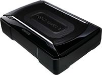
|
Image |
|---|---|
| Kenwood KSC-SW11. |
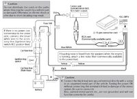
The wiring for both Kenwoods is identical, and I planned to used phono leads to connect to the head unit.
|
Wiring Diagram |
|---|---|
| Kenwood KSC-SW11. |
I have a fairly basic Alpine CDE-9872RM

|
Image |
|---|---|
| Alpine CDE-9872RM |
So consulting the wiring diagram there are basically 5 connections to consider.
+ve Power
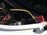
Litton4 had suggested to me that he believed the power for his subwoofer had come from the jump start posts under the inspection hatch. After a quick reccie I found the fuse box and obviously plenty of cables leaving that area and heading into the cabin. Having a look under the pax footwell I spotted a bundle of cables heading out through a grommet just underneath where I imagined the fuse box to be... so i small incision into the grommet and a poke of a graphite rod (technical version of a coat hanger) I found it appearing underneath the fuse box. This confirmed I had a run for +ve and earth. SO starting from the outside in (yellow power cable for the sub has a separate 10amp fuse near the O ring connector I duck taped the other end to my rod and retrieved it into the cabin. (easier to remove the fuse box to get access and be careful not to lose the nylon washers underneath) Ok so 1 cable down.
Earth
So the +ve cable separates from the block/plug thing with m/f bullet conectors. The earth however is two cables into one and is connected to a block that accommodates the other connectors and won't practically squeeze through a grommet. The +ve is such a long cable you can easily attach the earth to it (more duck tape) and then retrieve it by pulling the yellow power cable from the outside. Bingo. 2 cables done.
|
Image |
|---|---|
| +ve and earth connected to jump start posts |
I had to swing the +ve cable around so I could put the red insulation cover back on.. (I also dropped the original nut somewhere onto the floor pan. Doh!)
Phono cables
So the next connundrum is how to connect the Phono and blue/white 'trigger' cable to the head unit.
|
Image |
|---|---|
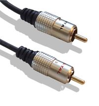
| 2m phono cables |
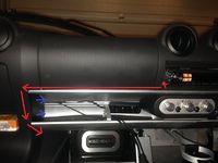
This was much trial and error and after a failed attempt trying to poke them up through another grommet I discovered there's a track that runs along the top oddments tray and below the airbag part of the dash (long red horizontal arrow)
I removed the side panel in the direction of the blue arrows (unclip it from the front edge gently) and clearly you will need to extract the head unit at some point. Now is a good time as I found I also needed to remove the cage. This is because there is a recess underneath the cage on either side that will enable you to gets the phono and power control cables discreetly to the back to the unit underneath it without impeding the HU. So you can poke the phono cables from right to left or left to right but along the red arrows.
Power Control Cables
The Power control cable (blue/white) will need to go left to right as they are connected to the plug. With the cage out you'll find a gap big enough to poke them backwards and you can put the cage back.
|
Image |
|---|---|
| cable run behind airbag fasica |
Remote control
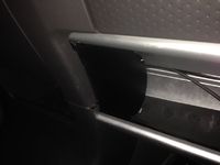
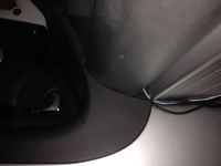
With the blue panel out you could also locate the remote unit into the cubby shelf and I used the groove in the rear as a cable run for the telephone style cable. All these leads can then be routed down behind the side trim and for it to emerge just underneath.
|
Image |
|---|---|
| Cables hidden behind side panel |
|
Image |
|---|---|
| Cables emerge under shelf |
So now you have the cable for the remote with the telephone plug to plug in directly to the subwoofer and the two phono connectors to mate into the ones from the block connector. The +ve cable should connect using the bullet connectors the earth goes straight to the block.
Head Unit connections
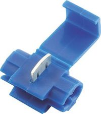
There should be only 2/3 connections to do. The phono ones are simple right and left. The CDE-9872RM does not have a power control terminal and so I crimped it onto the red power connector from the head unit using a quick splice electrical connector (I had the wiring diagram from the manual to confirm)
|
Image |
|---|---|
| Quick Splice electrical connector |
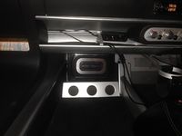
So now to test. Presuming it's all working you can now work on how to fix it to the wall. There's a nasty big bolt on the Exige just where you don't need it and the wall isn't exactly flat so I used a load of super strong double sided tape. It may not be quite up to track abuse but if I find that's the case in the future I'll investigate some alternatives which may involve a drill!!!!! Some of the cables are long by design (to allow for other installations) so you'll have a lot of cable tieing to do to tidy up the excess.
|
Image |
|---|---|
| In situe, time to tweak the settings and tidy the cables |