Difference between revisions of "Fusebox"
m |
Lithopsian (talk | contribs) (I wrote this - I don't know why and I withdraw it - add back if you think it is the case) |
||
| (53 intermediate revisions by 11 users not shown) | |||
| Line 1: | Line 1: | ||
| − | + | ==Fuses== | |
| − | Fuses protect your car from electrical short circuits and power overloads that can damage equipment or start a fire. Often, a fuse will blow due to a momentary overload, and replacing the bad fuse as directed below will fix the problem (the car's horn or interior lights may cease to work, for example). If a fuse blows repeatedly, it indicates an electrical problem that will require a trip to your Lotus Dealer. | + | Fuses protect your car from electrical short circuits and power overloads that can damage equipment or start a fire. Often, a fuse will blow due to a momentary overload, and replacing the bad fuse as directed below will fix the problem (the car's horn or interior lights may cease to work, for example). If a fuse blows repeatedly, it indicates an electrical problem that will require a little trip to your Lotus Dealer. The wires can corrode on the reverse of the fusebox and break off. If this happens new clip in fuse terminals can be sourced from Smart car dealers, part number 011 545 84 26 or 004 545 52 26, both parts numbers are correct. Simply solder them onto the wire and push fit them into a spare socket in the fusebox, then mark up your handbook with the change. |
'''Never replace a fuse with one of bigger amperage. This could damage the device the fuse is meant to protect.''' | '''Never replace a fuse with one of bigger amperage. This could damage the device the fuse is meant to protect.''' | ||
| − | + | [[image:fuses.JPG|thumb|left|'Littel' coloured fuses]] | |
| − | [[image:fuses.JPG|thumb|left|' | ||
{{clr}} | {{clr}} | ||
| + | ==Fuse Colours== | ||
| + | ;Regular blade fuses | ||
| + | * '''2A''' = BLACK (the owner's manual says black, but 1A fuses are black; 2A are paler and usually referred to as grey) | ||
| + | * '''3A''' = VIOLET | ||
| + | * '''4A''' = PINK | ||
| + | * '''5A''' = ORANGE (officially "tan" or "beige", in practice anything between orange and brown) | ||
| + | * '''7.5A''' = BROWN | ||
| + | * '''10A''' = RED | ||
| + | * '''15A''' = LIGHT BLUE | ||
| + | * '''20A''' = YELLOW | ||
| + | * '''25A''' = CLEAR | ||
| − | + | ;Maxi fuses | |
| − | + | * '''25A''' = GREY | |
| − | + | * '''30A''' = GREEN | |
| − | ''' | + | * '''40A''' = ORANGE ("amber") |
| − | + | * '''50A''' = RED | |
| − | ''' | ||
| − | |||
| − | ''' | ||
| − | |||
| − | |||
| − | |||
| − | |||
| − | |||
| − | ''' | ||
| − | |||
| − | |||
| − | |||
| − | |||
| − | |||
| − | |||
| + | ==Elise== | ||
===Elise S1 Fuse Box=== | ===Elise S1 Fuse Box=== | ||
| − | The main fusebox is located in the front | + | The main fusebox is located in the front under the bonnet, on the passenger side, and is protected by a plastic cover. Twenty two slots are provided for standard size 'Littelfuse' 257 series blade fuses which are numbered, and [[Fusebox#Fuse Colours|coloured]] according to their amperage rating, and may be pulled out from their slots using the fuse extractor tool provided on the fusebox lid. |
[[image:s1mainfuses.JPG|thumb|left|S1 Main Fuse Box]] | [[image:s1mainfuses.JPG|thumb|left|S1 Main Fuse Box]] | ||
{{clr}} | {{clr}} | ||
| − | |||
{| cellpadding="8" cellspacing="0" border="1" | {| cellpadding="8" cellspacing="0" border="1" | ||
|'''Slot''' | |'''Slot''' | ||
| − | |''' | + | |'''Rating''' |
|align="right"|'''Circuit''' | |align="right"|'''Circuit''' | ||
|- | |- | ||
|1 | |1 | ||
|3A | |3A | ||
| − | |align="right"|Rear | + | |align="right"|Rear fog lamp |
|- | |- | ||
|2 | |2 | ||
| Line 72: | Line 67: | ||
|7 | |7 | ||
|10A | |10A | ||
| − | |align="right"|Ignition services | + | |align="right"|Ignition services<br/>(cooling fan relay, switch illumination,<br/> alternator exciter, immobiliser, radio, Stack) |
|- | |- | ||
|8 | |8 | ||
|7.5A | |7.5A | ||
| − | |align="right"|Stop lamps & Battery services | + | |align="right"|Stop lamps & Battery services<br/>(horn relay, OBD2, Stack) |
|- | |- | ||
|9 | |9 | ||
| Line 112: | Line 107: | ||
|17 | |17 | ||
|5A | |5A | ||
| − | |align="right"|Sidelamp | + | |align="right"|Sidelamp RH |
|- | |- | ||
|18 | |18 | ||
| Line 124: | Line 119: | ||
|20 | |20 | ||
|20A | |20A | ||
| − | |align="right"| | + | |align="right"|Fast fan speed relay (A/C only) |
|- | |- | ||
|21 | |21 | ||
| Line 133: | Line 128: | ||
|BLANK | |BLANK | ||
|align="right"|BLANK | |align="right"|BLANK | ||
| + | |} | ||
| + | |||
| + | Early Elises (pre Oct 97) have several fuse boxes. The main one is located on the left hand side of the front services compartment. A smaller fuse box is located underneath the windscreen motor cover. | ||
| + | |||
| + | {| cellpadding="8" cellspacing="0" border="1" | ||
| + | |'''Slot''' | ||
| + | |'''Rating''' | ||
| + | |align="right"|'''Circuit''' | ||
| + | |- | ||
| + | |1 | ||
| + | |3A | ||
| + | |align="right"|Rear fog lamp | ||
| + | |- | ||
| + | |2 | ||
| + | |2A | ||
| + | |align="right"|Alarm | ||
| + | |- | ||
| + | |3 | ||
| + | |15A | ||
| + | |align="right"|Interior fan | ||
| + | |- | ||
| + | |4 | ||
| + | |15A | ||
| + | |align="right"|Wiper motor | ||
| + | |- | ||
| + | |5 | ||
| + | |3A | ||
| + | |align="right"|Reverse lamp | ||
| + | |- | ||
| + | |6 | ||
| + | |7.5A | ||
| + | |align="right"|Direction indicators | ||
| + | |- | ||
| + | |7 | ||
| + | |5A | ||
| + | |align="right"|Ignition services | ||
| + | |- | ||
| + | |8 | ||
| + | |7.5A | ||
| + | |align="right"|Stop lamps & Battery services | ||
| + | |- | ||
| + | |9 | ||
| + | |10A | ||
| + | |align="right"|Hazard lamps | ||
| + | |- | ||
| + | |10 | ||
| + | |7.5A | ||
| + | |align="right"|Horn | ||
| + | |- | ||
| + | |11 | ||
| + | |10A | ||
| + | |align="right"|Alarm & Interior lamp | ||
| + | |- | ||
| + | |12 | ||
| + | |25A | ||
| + | |align="right"|Cooling fan | ||
| + | |} | ||
| + | |||
| + | Fusebox under wiper motor | ||
| + | |||
| + | {| cellpadding="8" cellspacing="0" border="1" | ||
| + | |'''Slot''' | ||
| + | |'''Rating''' | ||
| + | |align="right"|'''Circuit''' | ||
| + | |- | ||
| + | |13 | ||
| + | |20A | ||
| + | |align="right"|Radio | ||
| + | |- | ||
| + | |14 | ||
| + | |20A | ||
| + | |align="right"|Cigar lighter | ||
| + | |- | ||
| + | |15 | ||
| + | |5A | ||
| + | |align="right"|Sidelamp LH | ||
| + | |- | ||
| + | |16 | ||
| + | |5A | ||
| + | |align="right"|Sidelamp RH | ||
|} | |} | ||
{{clr}} | {{clr}} | ||
| + | |||
| + | ===Elise S1 fuel pump fuse=== | ||
| + | The fuel pump fuse is located near the ECU at the rear of the car. In the later bootbox cars, there is a 20A fuse inside the engine compartment but accessible through a hole under the carpet on the LH side near the inertia switch. In earlier cars, there is a 10A fuse inside the boot next to the ECU. | ||
===Elise S1 Relays=== | ===Elise S1 Relays=== | ||
| − | |||
{| cellpadding="8" cellspacing="0" border="1" | {| cellpadding="8" cellspacing="0" border="1" | ||
| Line 154: | Line 231: | ||
|} | |} | ||
{{clr}} | {{clr}} | ||
| − | |||
===Elise S1 Maxi Fuses=== | ===Elise S1 Maxi Fuses=== | ||
| − | Also on the | + | Also on the Elise are three Maxi fuses. Two maxi fuses are located in the front service compartment, beneath the wiper motor protective cover. |
[[image:s1maxi.JPG|thumb|left|Maxi Fuses]] | [[image:s1maxi.JPG|thumb|left|Maxi Fuses]] | ||
{{clr}} | {{clr}} | ||
| − | |||
{| cellpadding="8" cellspacing="0" border="1" | {| cellpadding="8" cellspacing="0" border="1" | ||
| Line 172: | Line 247: | ||
|} | |} | ||
{{clr}} | {{clr}} | ||
| + | |||
| + | There is a third 40A maxi fuse for the engine management system, including the starter motor relay. Prior to about February 1997, a 1.0 kW starter motor was used and the maxi fuse is in the boot next the ECU. Later cars have a 1.4 kW starter motor and a maxi fuse under the wiper motor cover. | ||
===K Series Elise S2 Fuse Box=== | ===K Series Elise S2 Fuse Box=== | ||
| − | The main fusebox is located in the front [[services compartment]], on the passenger side, and is protected by a clear plastic cover. For access, remove the passenger side front body [[access panel]], followed by the radiator air deflector panel. Twenty two slots are provided for ' | + | The main fusebox is located in the front [[services compartment]], on the passenger side, and is protected by a clear plastic cover. For access, remove the passenger side front body [[access panel]], followed by the radiator air deflector panel: |
| + | |||
| + | [[image:radiator_air_deflector_panel.JPG|thumb|left|Radiator air deflector panel (LHD)]] | ||
| + | {{clr}} | ||
| + | |||
| + | |||
| + | Twenty two slots are provided for standard size 'Littelfuse' 257 series blade fuses which are numbered, and [http://wiki.seloc.org/index.php/Fuse_box#Fuse_Colours coloured] according to their amperage rating, and may be pulled out from their slots useing the fuse extractor tool provided on the fusebox lit. | ||
| + | |||
| + | |||
| + | [[image:s2fusebox.JPG|thumb|left|S2 Fusebox (RHD)]] | ||
| + | {{clr}} | ||
| − | [[image: | + | [[image:S2 fuses.jpg|thumb|left|S2 Fusebox (LHD)]] |
{{clr}} | {{clr}} | ||
| Line 237: | Line 324: | ||
|13 | |13 | ||
|7.5A | |7.5A | ||
| − | |align="right"| | + | |align="right"|Audio ignition |
|- | |- | ||
|14 | |14 | ||
| Line 280: | Line 367: | ||
===K Series Elise S2 Relays=== | ===K Series Elise S2 Relays=== | ||
| − | Fuses and relays associated with the engine management system are located at the rear of the engine bay adjacent to the engine ECM. The mulit-function relay unit containing the engine control relay and starter relay is mounted on the chassis rear subframe below the engine ECM. | + | Fuses and relays associated with the engine management system are located at the rear of the engine bay adjacent to the engine [[ECM]]. The mulit-function relay unit containing the engine control relay and starter relay is mounted on the chassis rear subframe below the engine [[ECM]]. |
{| cellpadding="8" cellspacing="0" border="1" | {| cellpadding="8" cellspacing="0" border="1" | ||
| Line 319: | Line 406: | ||
|'''3''' | |'''3''' | ||
|20A | |20A | ||
| − | |align="right"| | + | |align="right"|Start immobiliser |
|- | |- | ||
|'''4''' | |'''4''' | ||
| Line 329: | Line 416: | ||
|align="right"|Alternator output | |align="right"|Alternator output | ||
|} | |} | ||
| − | |||
| − | |||
===Toyota Elise S2 Fuse Box=== | ===Toyota Elise S2 Fuse Box=== | ||
| Line 338: | Line 423: | ||
{{clr}} | {{clr}} | ||
| + | The main fusebox is located in the front [[services compartment]], on the passenger side, and is protected by a clear plastic cover. For access, remove the passenger side front body [[access panel]], followed by the radiator air deflector panel. Twenty two slots are provided for standard size 'Littelfuse' 257 series blade fuses which are numbered, and [http://wiki.seloc.org/index.php/Fuse_box#Fuse_Colours coloured] according to their amperage rating, and may be pulled out from their slots useing the fuse extractor tool provided on the fusebox lit. | ||
| − | |||
| + | {| cellpadding="8" cellspacing="0" border="1" | ||
| + | |'''Slot''' | ||
| + | |'''Raiting''' | ||
| + | |align="right"|'''Circuit''' | ||
| + | |- | ||
| + | |1 | ||
| + | |20A | ||
| + | |align="right"|Aux. power socket | ||
| + | |- | ||
| + | |2 | ||
| + | |2A | ||
| + | |align="right"|non USA:alarm siren USA:reverse lamps | ||
| + | |- | ||
| + | |3 | ||
| + | |20A | ||
| + | |align="right"|driver window | ||
| + | |- | ||
| + | |4 | ||
| + | |20A | ||
| + | |align="right"|Passange window | ||
| + | |- | ||
| + | |5 | ||
| + | |7.5A | ||
| + | |align="right"|non USA:Reverse lamps USA:Stoplamps | ||
| + | |- | ||
| + | |6 | ||
| + | |7.5A | ||
| + | |align="right"|Turn indicators | ||
| + | |- | ||
| + | |7 | ||
| + | |10A | ||
| + | |align="right"|Ignition services | ||
| + | |- | ||
| + | |8 | ||
| + | |7.5A | ||
| + | |align="right"|Battery services | ||
| + | |- | ||
| + | |9 | ||
| + | |10A | ||
| + | |align="right"|Hazard lamps | ||
| + | |- | ||
| + | |10 | ||
| + | |7.5A | ||
| + | |align="right"|Horn | ||
| + | |- | ||
| + | |11 | ||
| + | |10A | ||
| + | |align="right"|Alarm & Interior lamp | ||
| + | |- | ||
| + | |12 | ||
| + | |10A | ||
| + | |align="right"|ABS | ||
| + | |- | ||
| + | |13 | ||
| + | |3A | ||
| + | |align="right"|[[ECU]] ignition | ||
| + | |- | ||
| + | |14 | ||
| + | |20A | ||
| + | |align="right"|Radiator fans 1 fast & 2 slow | ||
| + | |- | ||
| + | |15 | ||
| + | |7.5A | ||
| + | |align="right"|Radio, switch pack module | ||
| + | |- | ||
| + | |16 | ||
| + | |10A | ||
| + | |align="right"|non USA:Rear fog USA:Sidelamps | ||
| + | |- | ||
| + | |17 | ||
| + | |10A | ||
| + | |align="right"|Dip beam LH | ||
| + | |- | ||
| + | |18 | ||
| + | |10A | ||
| + | |align="right"|Dip beam RH | ||
| + | |- | ||
| + | |19 | ||
| + | |20A | ||
| + | |align="right"|A.C comp relay & rad fan 2 fast | ||
| + | |- | ||
| + | |20 | ||
| + | |15A | ||
| + | |align="right"|Main beam LH | ||
| + | |- | ||
| + | |21 | ||
| + | |15A | ||
| + | |align="right"|Main beam RH | ||
| + | |- | ||
| + | |22 | ||
| + | |7.5 | ||
| + | |align="right"|CDL | ||
| + | |} | ||
| − | |||
{{clr}} | {{clr}} | ||
| − | |||
| − | [[image: | + | [[image:fuseview.JPG|thumb|left|Overhead View of the fusebox]] |
{{clr}} | {{clr}} | ||
| + | ===Toyota Elise S2 Interior Fuses & Relays=== | ||
The wash/wipe module, turn/hazard flasher relay, horn relay and a relay for inertia switch activation of the central door locking, are mounted on the scuttle beam above the passenger footwell, with four fuses secured to the harness in that area. | The wash/wipe module, turn/hazard flasher relay, horn relay and a relay for inertia switch activation of the central door locking, are mounted on the scuttle beam above the passenger footwell, with four fuses secured to the harness in that area. | ||
| − | A 60A Maxi fuse protecting the ABS circuit is located beneath the passenger side fascia top, adjacent to the positive post. A multi-function relay unit containing the engine control relay, fuel pump relay and starter relay is mounted in | + | A 60A Maxi fuse protecting the ABS circuit is located beneath the passenger side fascia top, adjacent to the positive post. A multi-function relay unit containing the engine control relay, fuel pump relay and starter relay is mounted in the engine bay near the [[ECU]]. A similar relay unit is mounted in the front services compartment alongside the fusebox, and operates the a.c. compressor and radiator fans. |
| − | the engine bay near the ECU. A similar relay unit is mounted in the front services compartment alongside the fusebox, and operates the a.c. compressor and radiator fans. | + | |
| + | [[image:yodainsidefuses.JPG|thumb|left|Interior fuses]] | ||
| + | {{clr}} | ||
'''Important Note: Although the two modules are identical in appearance, their function is different and they must not be transposed.''' | '''Important Note: Although the two modules are identical in appearance, their function is different and they must not be transposed.''' | ||
| Line 361: | Line 540: | ||
The A.C. relay module A117M0038F has a brown label marked YWB100800. | The A.C. relay module A117M0038F has a brown label marked YWB100800. | ||
| − | The engine relay module | + | The engine relay module A111M6024F has a white label marked YWB100970. |
| + | |||
| + | {| cellpadding="8" cellspacing="0" border="1" | ||
| + | |'''C1''' | ||
| + | |20A | ||
| + | |align="right"|Interior fan | ||
| + | |- | ||
| + | |'''C2''' | ||
| + | |15A | ||
| + | |align="right"|Wiper motor | ||
| + | |- | ||
| + | |'''C3''' | ||
| + | |7.5A | ||
| + | |align="right"|Audio key-in | ||
| + | |- | ||
| + | |'''C4''' | ||
| + | |10A | ||
| + | |align="right"|A.C. compressor | ||
| + | |} | ||
| + | {{clr}} | ||
===Toyota Elise S2 Engine Fuses=== | ===Toyota Elise S2 Engine Fuses=== | ||
| − | Fuses and relays associated with the engine management system are contained in two 4-position fuse holders located at the front of the engine bay on the cabin bulkhead, adjacent to the engine ECM. To access the fuses, unclip rear edge of the cover. | + | Fuses and relays associated with the engine management system are contained in two 4-position fuse holders located at the front of the engine bay on the cabin bulkhead, adjacent to the engine [[ECM]]. To access the fuses, unclip rear edge of the cover. |
[[image:yodaenginefuses.JPG|thumb|left|Engine Fuses]] | [[image:yodaenginefuses.JPG|thumb|left|Engine Fuses]] | ||
| Line 372: | Line 570: | ||
| + | {| cellpadding="8" cellspacing="0" border="1" | ||
| + | |'''R1''' | ||
| + | |20A | ||
| + | |align="right"|Fuel pump | ||
| + | |- | ||
| + | |'''R2''' | ||
| + | |3A | ||
| + | |align="right"|Immobiliser | ||
| + | |- | ||
| + | |'''R3''' | ||
| + | |5A | ||
| + | |align="right"|Alternator sense | ||
| + | |- | ||
| + | |'''R4''' | ||
| + | |5A | ||
| + | |align="right"|[[ECU]] battery feed | ||
| + | |- | ||
| + | |'''R5''' | ||
| + | |5A | ||
| + | |align="right"|O2 heaters | ||
| + | |- | ||
| + | |'''R6''' | ||
| + | |7.5A | ||
| + | |align="right"|VSV's VVT, VVL, IAC | ||
| + | |- | ||
| + | |'''R7''' | ||
| + | |10A | ||
| + | |align="right"|Injectors, ignition coils | ||
| + | |- | ||
| + | |'''R8''' | ||
| + | |5A | ||
| + | |align="right"|Re-circ. pump | ||
| + | |- | ||
| + | |} | ||
| + | {{clr}} | ||
| + | |||
| + | ==Evora== | ||
| + | |||
| + | ===Main Fusebox=== | ||
| + | |||
| + | The main fuse and relay boxes are located at the front of the passenger footwell, protected by a removable panel secured by a quarter turn fastener at each top corner, and a location channel on the floor. Forty slots are provided for mini fuses which are numbered, and coloured according to their amperage rating, and may be pulled out from their slots using the fuse extractor tool clipped to the fusebox. Six maxi fuses protecting major circuits are also provided, along with six single contact change over micro relays and two 50A power relays. | ||
| + | |||
| + | [[image:Evora - Main Fuse Box.png|thumb|left|Evora Main Fuse Box]] | ||
| + | {{clr}} | ||
| + | |||
| + | {| cellpadding="8" cellspacing="0" border="1" | ||
| + | ! Slot | ||
| + | | '''Rate''' | ||
| + | | '''Circuit''' | ||
| + | ! Slot | ||
| + | | '''Rate''' | ||
| + | | '''Circuit''' | ||
| + | ! Slot | ||
| + | | '''Rate''' | ||
| + | | '''Circuit''' | ||
| + | |- | ||
| + | ! C1 | ||
| + | | 10A | ||
| + | | Horn | ||
| + | ! C21 | ||
| + | | 3A | ||
| + | | Ignition Services | ||
| + | ! MC1 | ||
| + | | 40A | ||
| + | | Battery Positive | ||
| + | |- | ||
| + | ! C2 | ||
| + | | 5A | ||
| + | | Battery Services | ||
| + | ! C22 | ||
| + | | 5A | ||
| + | | ABS | ||
| + | ! MC1 | ||
| + | | 40A | ||
| + | | B+, ignition | ||
| + | |- | ||
| + | ! C3 | ||
| + | | 7.5A | ||
| + | | CDL, Alarm B+ | ||
| + | ! C23 | ||
| + | | 3A | ||
| + | | Homelink | ||
| + | ! MC3 | ||
| + | | 40A | ||
| + | | Accessories | ||
| + | |- | ||
| + | ! C4 | ||
| + | | 20A | ||
| + | | Rad fan relay 1 | ||
| + | ! C24 | ||
| + | | 3A | ||
| + | | Brake lamps | ||
| + | ! MC4 | ||
| + | | 40A | ||
| + | | ABS B+ | ||
| + | |- | ||
| + | ! C5 | ||
| + | | 20A | ||
| + | | Rad fan relay 3 | ||
| + | ! C25 | ||
| + | | 15A | ||
| + | | HL powerwash | ||
| + | ! MC5 | ||
| + | | 25A | ||
| + | | ABS B+ | ||
| + | |- | ||
| + | ! C6 | ||
| + | | 10A | ||
| + | | Radio B+ | ||
| + | ! C26 | ||
| + | | 5A | ||
| + | | Alarm ignition | ||
| + | ! MC6 | ||
| + | | 25A | ||
| + | | HRS | ||
| + | |- | ||
| + | ! C7 | ||
| + | | 5A | ||
| + | | Key-in relay | ||
| + | ! C27 | ||
| + | | - | ||
| + | | - | ||
| + | |- | ||
| + | ! C8 | ||
| + | | 2A | ||
| + | | Ignition switch | ||
| + | ! C28 | ||
| + | | 7.5A | ||
| + | | HVAC ignition | ||
| + | |- | ||
| + | ! C9 | ||
| + | | 20A | ||
| + | | Driver's window | ||
| + | ! C29 | ||
| + | | 5A | ||
| + | | Washer jets | ||
| + | |- | ||
| + | ! C10 | ||
| + | | 20A | ||
| + | | Passenger's window | ||
| + | ! C30 | ||
| + | | 5A | ||
| + | | SRS unit | ||
| + | |- | ||
| + | ! C11 | ||
| + | | 7.5A | ||
| + | | Hazard & Turn | ||
| + | ! C31 | ||
| + | | 3A | ||
| + | | Heated mirrors | ||
| + | |- | ||
| + | ! C12 | ||
| + | | 3A | ||
| + | | Interior lighting | ||
| + | ! C32 | ||
| + | | 5A | ||
| + | | Washer pump | ||
| + | |- | ||
| + | ! C13 | ||
| + | | 20A | ||
| + | | Int. control mod. | ||
| + | ! C33 | ||
| + | | 5A | ||
| + | | Mirror/window sw. | ||
| + | |- | ||
| + | ! C14 | ||
| + | | 3A | ||
| + | | Footwell lamps | ||
| + | ! C34 | ||
| + | | 20A | ||
| + | | Wiper Motor | ||
| + | |- | ||
| + | ! C15 | ||
| + | | 5A | ||
| + | | LH sidelamps | ||
| + | ! C35 | ||
| + | | - | ||
| + | | - | ||
| + | |- | ||
| + | ! C16 | ||
| + | | 5A | ||
| + | | RH sidelamps | ||
| + | ! C36 | ||
| + | | 20A | ||
| + | | Interior fan | ||
| + | |- | ||
| + | ! C17 | ||
| + | | 15A | ||
| + | | LH headlamp | ||
| + | ! C37 | ||
| + | | 10A | ||
| + | | Cabin power socket | ||
| + | |- | ||
| + | ! C18 | ||
| + | | 15A | ||
| + | | RH headlamp | ||
| + | ! C38 | ||
| + | | - | ||
| + | | - | ||
| + | |- | ||
| + | ! C19 | ||
| + | | 15A | ||
| + | | Main beam | ||
| + | ! C39 | ||
| + | | - | ||
| + | | - | ||
| + | |- | ||
| + | ! C20 | ||
| + | | 3A | ||
| + | | Rear foglamp | ||
| + | ! C40 | ||
| + | | - | ||
| + | | - | ||
| + | |- | ||
| + | |} | ||
| + | |||
| + | ===Relays=== | ||
| + | |||
| + | Mounted on the front fusebox panel, is a block of relays, the layout of which is inverted for opposite drive hands: | ||
| + | |||
| + | [[image:Evora - Front Relay Blocks.png|thumb|left|Evora Main Fuse Box]] | ||
{{clr}} | {{clr}} | ||
| + | ===Rear Fusebox=== | ||
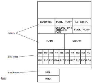
| + | Fuses and relays for the engine bay and rear mounted systems are contained in a fusebox mounted in the cabin, behind the left hand rear quarter trim panel. For access, use a coin to release the quarter turn fastener on the lower edge of the removable panel, and unhook the top edge. Twenty slots are provided for mini fuses which are numbered, and coloured according to their amperage rating, and may be pulled out from their slots using the fuse extractor tool clipped to the fusebox. Two maxi fuses protecting major circuits are also provided, along with four single contact change over micro relays, and two power relays. | ||
| + | [[image:Evora - Rear Fuse Box.png|thumb|left|Evora Main Fuse Box]] | ||
| + | {{clr}} | ||
| + | {| cellpadding="8" cellspacing="0" border="1" | ||
| + | ! Slot | ||
| + | | '''Rate''' | ||
| + | | '''Circuit''' | ||
| + | ! Slot | ||
| + | | '''Rate''' | ||
| + | | '''Circuit''' | ||
| + | ! Slot | ||
| + | | '''Rate''' | ||
| + | | '''Circuit''' | ||
| + | |- | ||
| + | ! R1 | ||
| + | | 10A | ||
| + | | ECU, fan relay 3 | ||
| + | ! R11 | ||
| + | | 7.5A | ||
| + | | A.c. compressor | ||
| + | ! MR1 | ||
| + | | 30A | ||
| + | | Crank & main relay | ||
| + | |- | ||
| + | ! R2 | ||
| + | | 7.5A | ||
| + | | Injectors | ||
| + | ! R12 | ||
| + | | 3A | ||
| + | | Rev lamp, camera | ||
| + | ! MR2 | ||
| + | | 30A | ||
| + | | Busbar R17-R20 | ||
| + | |- | ||
| + | ! R3 | ||
| + | | 10A | ||
| + | | Ignition coils | ||
| + | ! R13 | ||
| + | | - | ||
| + | | - | ||
| + | |- | ||
| + | ! R4 | ||
| + | | 2A | ||
| + | | Re-circ. pump | ||
| + | ! R14 | ||
| + | | 10A | ||
| + | | Engine bay fan | ||
| + | |- | ||
| + | ! R5 | ||
| + | | - | ||
| + | | - | ||
| + | ! R15 | ||
| + | | 3A | ||
| + | | Boot lamps | ||
| + | |- | ||
| + | ! R6 | ||
| + | | - | ||
| + | | - | ||
| + | ! R16 | ||
| + | | 10A | ||
| + | | Boot power socket | ||
| + | |- | ||
| + | ! R7 | ||
| + | | 5A | ||
| + | | ECU ignition | ||
| + | ! R17 | ||
| + | | 20A | ||
| + | | Amplifier | ||
| + | |- | ||
| + | ! R8 | ||
| + | | 7.5A | ||
| + | | Engine solenoids | ||
| + | ! R18 | ||
| + | | 5A | ||
| + | | Fuel filler flap | ||
| + | |- | ||
| + | ! R9 | ||
| + | | 5A | ||
| + | | O2 heaters | ||
| + | ! R19 | ||
| + | | 10A | ||
| + | | Fuel pump | ||
| + | |- | ||
| + | ! R10 | ||
| + | | 5A | ||
| + | | Alternator ign. | ||
| + | ! R20 | ||
| + | | 5A | ||
| + | | Alternator B+ | ||
| + | |- | ||
| + | |} | ||
| + | ==References== | ||
| + | [http://en.wikipedia.org/wiki/Fuse_box Wikipedia On Fuse Boxes] | ||
| − | [ | + | [[Category:Electrical]] |
| + | [[Category:Lotus Elise]] | ||
| + | [[Category:Lotus Evora]] | ||
| + | [[Category:S1]] | ||
| + | [[Category:S2]] | ||
Latest revision as of 12:02, 5 February 2023
Fuses
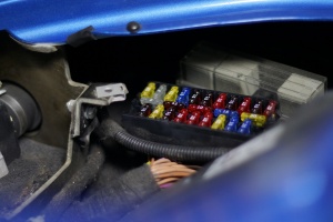
Fuses protect your car from electrical short circuits and power overloads that can damage equipment or start a fire. Often, a fuse will blow due to a momentary overload, and replacing the bad fuse as directed below will fix the problem (the car's horn or interior lights may cease to work, for example). If a fuse blows repeatedly, it indicates an electrical problem that will require a little trip to your Lotus Dealer. The wires can corrode on the reverse of the fusebox and break off. If this happens new clip in fuse terminals can be sourced from Smart car dealers, part number 011 545 84 26 or 004 545 52 26, both parts numbers are correct. Simply solder them onto the wire and push fit them into a spare socket in the fusebox, then mark up your handbook with the change.
Never replace a fuse with one of bigger amperage. This could damage the device the fuse is meant to protect.
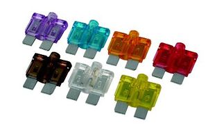
Fuse Colours
- Regular blade fuses
- 2A = BLACK (the owner's manual says black, but 1A fuses are black; 2A are paler and usually referred to as grey)
- 3A = VIOLET
- 4A = PINK
- 5A = ORANGE (officially "tan" or "beige", in practice anything between orange and brown)
- 7.5A = BROWN
- 10A = RED
- 15A = LIGHT BLUE
- 20A = YELLOW
- 25A = CLEAR
- Maxi fuses
- 25A = GREY
- 30A = GREEN
- 40A = ORANGE ("amber")
- 50A = RED
Elise
Elise S1 Fuse Box
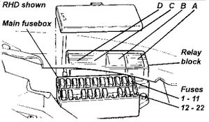
The main fusebox is located in the front under the bonnet, on the passenger side, and is protected by a plastic cover. Twenty two slots are provided for standard size 'Littelfuse' 257 series blade fuses which are numbered, and coloured according to their amperage rating, and may be pulled out from their slots using the fuse extractor tool provided on the fusebox lid.
| Slot | Rating | Circuit |
| 1 | 3A | Rear fog lamp |
| 2 | 2A | Alarm ignition |
| 3 | 20A | Interior fan |
| 4 | 15A | Wiper motor |
| 5 | 3A | Reverse lamp |
| 6 | 7.5A | Direction indicators |
| 7 | 10A | Ignition services (cooling fan relay, switch illumination, alternator exciter, immobiliser, radio, Stack) |
| 8 | 7.5A | Stop lamps & Battery services (horn relay, OBD2, Stack) |
| 9 | 10A | Hazard lamps |
| 10 | 7.5A | Horn |
| 11 | 10A | Alarm & Interior lamp |
| 12 | 25A | Cooling fan |
| 13 | BLANK | BLANK |
| 14 | 20A | Audio |
| 15 | 20A | Cigar lighter |
| 16 | 5A | Sidelamp LH |
| 17 | 5A | Sidelamp RH |
| 18 | BLANK | BLANK |
| 19 | BLANK | BLANK |
| 20 | 20A | Fast fan speed relay (A/C only) |
| 21 | BLANK | BLANK |
| 22 | BLANK | BLANK |
Early Elises (pre Oct 97) have several fuse boxes. The main one is located on the left hand side of the front services compartment. A smaller fuse box is located underneath the windscreen motor cover.
| Slot | Rating | Circuit |
| 1 | 3A | Rear fog lamp |
| 2 | 2A | Alarm |
| 3 | 15A | Interior fan |
| 4 | 15A | Wiper motor |
| 5 | 3A | Reverse lamp |
| 6 | 7.5A | Direction indicators |
| 7 | 5A | Ignition services |
| 8 | 7.5A | Stop lamps & Battery services |
| 9 | 10A | Hazard lamps |
| 10 | 7.5A | Horn |
| 11 | 10A | Alarm & Interior lamp |
| 12 | 25A | Cooling fan |
Fusebox under wiper motor
| Slot | Rating | Circuit |
| 13 | 20A | Radio |
| 14 | 20A | Cigar lighter |
| 15 | 5A | Sidelamp LH |
| 16 | 5A | Sidelamp RH |
Elise S1 fuel pump fuse
The fuel pump fuse is located near the ECU at the rear of the car. In the later bootbox cars, there is a 20A fuse inside the engine compartment but accessible through a hole under the carpet on the LH side near the inertia switch. In earlier cars, there is a 10A fuse inside the boot next to the ECU.
Elise S1 Relays
| A | Horn |
| B | Cooling fan |
| C | Dip beam |
| D | Main beam |
Elise S1 Maxi Fuses
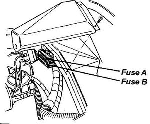
Also on the Elise are three Maxi fuses. Two maxi fuses are located in the front service compartment, beneath the wiper motor protective cover.
| A | Lighting |
| B | Ignition switch |
There is a third 40A maxi fuse for the engine management system, including the starter motor relay. Prior to about February 1997, a 1.0 kW starter motor was used and the maxi fuse is in the boot next the ECU. Later cars have a 1.4 kW starter motor and a maxi fuse under the wiper motor cover.
K Series Elise S2 Fuse Box
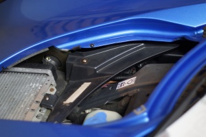
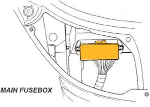
The main fusebox is located in the front services compartment, on the passenger side, and is protected by a clear plastic cover. For access, remove the passenger side front body access panel, followed by the radiator air deflector panel:
Twenty two slots are provided for standard size 'Littelfuse' 257 series blade fuses which are numbered, and coloured according to their amperage rating, and may be pulled out from their slots useing the fuse extractor tool provided on the fusebox lit.
| Slot | Raiting | Circuit |
| 1 | 20A | Aux. power socket |
| 2 | 2A | Alarm siren |
| 3 | 20A | Interior fan |
| 4 | 15A | Wiper motor |
| 5 | 7.5A | Stop lamp |
| 6 | 7.5A | Direction indicators |
| 7 | 10A | Ignition services |
| 8 | 7.5A | Battery services |
| 9 | 10A | Hazard lamps |
| 10 | 7.5A | Horn |
| 11 | 10A | Alarm power & Interior lamp |
| 12 | 25A | Cooling fan |
| 13 | 7.5A | Audio ignition |
| 14 | BLANK | BLANK |
| 15 | 7.5A | Audio +ve; switch module |
| 16 | 10A | Sidelamps;rear fog |
| 17 | 10A | Dip beam LH |
| 18 | 10A | Dip beam RH |
| 19 | BLANK | BLANK |
| 20 | 15A | Main beam LH |
| 21 | 15A | Main beam RH |
| 22 | BLANK | BLANK |
K Series Elise S2 Relays
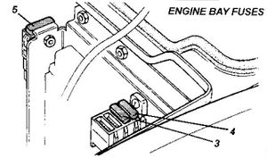
Fuses and relays associated with the engine management system are located at the rear of the engine bay adjacent to the engine ECM. The mulit-function relay unit containing the engine control relay and starter relay is mounted on the chassis rear subframe below the engine ECM.
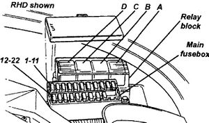
| A | Horn |
| B | Cooling fan |
| C | BLANK |
| D | BLANK |
K Series Elise S2 Engine Fuses
| Slot | Rating | Circit |
| 1 | BLANK | BLANK |
| 2 | BLANK | BLANK |
| 3 | 20A | Start immobiliser |
| 4 | 20A | Fuel pump |
| 5 | 80A | Alternator output |
Toyota Elise S2 Fuse Box
The main fusebox is located in the front services compartment, on the passenger side, and is protected by a clear plastic cover. For access, remove the passenger side front body access panel, followed by the radiator air deflector panel. Twenty two slots are provided for standard size 'Littelfuse' 257 series blade fuses which are numbered, and coloured according to their amperage rating, and may be pulled out from their slots useing the fuse extractor tool provided on the fusebox lit.
| Slot | Raiting | Circuit |
| 1 | 20A | Aux. power socket |
| 2 | 2A | non USA:alarm siren USA:reverse lamps |
| 3 | 20A | driver window |
| 4 | 20A | Passange window |
| 5 | 7.5A | non USA:Reverse lamps USA:Stoplamps |
| 6 | 7.5A | Turn indicators |
| 7 | 10A | Ignition services |
| 8 | 7.5A | Battery services |
| 9 | 10A | Hazard lamps |
| 10 | 7.5A | Horn |
| 11 | 10A | Alarm & Interior lamp |
| 12 | 10A | ABS |
| 13 | 3A | ECU ignition |
| 14 | 20A | Radiator fans 1 fast & 2 slow |
| 15 | 7.5A | Radio, switch pack module |
| 16 | 10A | non USA:Rear fog USA:Sidelamps |
| 17 | 10A | Dip beam LH |
| 18 | 10A | Dip beam RH |
| 19 | 20A | A.C comp relay & rad fan 2 fast |
| 20 | 15A | Main beam LH |
| 21 | 15A | Main beam RH |
| 22 | 7.5 | CDL |
Toyota Elise S2 Interior Fuses & Relays
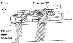
The wash/wipe module, turn/hazard flasher relay, horn relay and a relay for inertia switch activation of the central door locking, are mounted on the scuttle beam above the passenger footwell, with four fuses secured to the harness in that area.
A 60A Maxi fuse protecting the ABS circuit is located beneath the passenger side fascia top, adjacent to the positive post. A multi-function relay unit containing the engine control relay, fuel pump relay and starter relay is mounted in the engine bay near the ECU. A similar relay unit is mounted in the front services compartment alongside the fusebox, and operates the a.c. compressor and radiator fans.
Important Note: Although the two modules are identical in appearance, their function is different and they must not be transposed.
The A.C. relay module A117M0038F has a brown label marked YWB100800.
The engine relay module A111M6024F has a white label marked YWB100970.
| C1 | 20A | Interior fan |
| C2 | 15A | Wiper motor |
| C3 | 7.5A | Audio key-in |
| C4 | 10A | A.C. compressor |
Toyota Elise S2 Engine Fuses
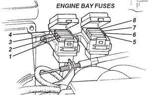
Fuses and relays associated with the engine management system are contained in two 4-position fuse holders located at the front of the engine bay on the cabin bulkhead, adjacent to the engine ECM. To access the fuses, unclip rear edge of the cover.
| R1 | 20A | Fuel pump |
| R2 | 3A | Immobiliser |
| R3 | 5A | Alternator sense |
| R4 | 5A | ECU battery feed |
| R5 | 5A | O2 heaters |
| R6 | 7.5A | VSV's VVT, VVL, IAC |
| R7 | 10A | Injectors, ignition coils |
| R8 | 5A | Re-circ. pump |
Evora
Main Fusebox
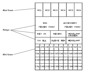
The main fuse and relay boxes are located at the front of the passenger footwell, protected by a removable panel secured by a quarter turn fastener at each top corner, and a location channel on the floor. Forty slots are provided for mini fuses which are numbered, and coloured according to their amperage rating, and may be pulled out from their slots using the fuse extractor tool clipped to the fusebox. Six maxi fuses protecting major circuits are also provided, along with six single contact change over micro relays and two 50A power relays.
| Slot | Rate | Circuit | Slot | Rate | Circuit | Slot | Rate | Circuit |
|---|---|---|---|---|---|---|---|---|
| C1 | 10A | Horn | C21 | 3A | Ignition Services | MC1 | 40A | Battery Positive |
| C2 | 5A | Battery Services | C22 | 5A | ABS | MC1 | 40A | B+, ignition |
| C3 | 7.5A | CDL, Alarm B+ | C23 | 3A | Homelink | MC3 | 40A | Accessories |
| C4 | 20A | Rad fan relay 1 | C24 | 3A | Brake lamps | MC4 | 40A | ABS B+ |
| C5 | 20A | Rad fan relay 3 | C25 | 15A | HL powerwash | MC5 | 25A | ABS B+ |
| C6 | 10A | Radio B+ | C26 | 5A | Alarm ignition | MC6 | 25A | HRS |
| C7 | 5A | Key-in relay | C27 | - | - | |||
| C8 | 2A | Ignition switch | C28 | 7.5A | HVAC ignition | |||
| C9 | 20A | Driver's window | C29 | 5A | Washer jets | |||
| C10 | 20A | Passenger's window | C30 | 5A | SRS unit | |||
| C11 | 7.5A | Hazard & Turn | C31 | 3A | Heated mirrors | |||
| C12 | 3A | Interior lighting | C32 | 5A | Washer pump | |||
| C13 | 20A | Int. control mod. | C33 | 5A | Mirror/window sw. | |||
| C14 | 3A | Footwell lamps | C34 | 20A | Wiper Motor | |||
| C15 | 5A | LH sidelamps | C35 | - | - | |||
| C16 | 5A | RH sidelamps | C36 | 20A | Interior fan | |||
| C17 | 15A | LH headlamp | C37 | 10A | Cabin power socket | |||
| C18 | 15A | RH headlamp | C38 | - | - | |||
| C19 | 15A | Main beam | C39 | - | - | |||
| C20 | 3A | Rear foglamp | C40 | - | - |
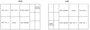
Relays
Mounted on the front fusebox panel, is a block of relays, the layout of which is inverted for opposite drive hands:
Rear Fusebox
Fuses and relays for the engine bay and rear mounted systems are contained in a fusebox mounted in the cabin, behind the left hand rear quarter trim panel. For access, use a coin to release the quarter turn fastener on the lower edge of the removable panel, and unhook the top edge. Twenty slots are provided for mini fuses which are numbered, and coloured according to their amperage rating, and may be pulled out from their slots using the fuse extractor tool clipped to the fusebox. Two maxi fuses protecting major circuits are also provided, along with four single contact change over micro relays, and two power relays.
| Slot | Rate | Circuit | Slot | Rate | Circuit | Slot | Rate | Circuit |
|---|---|---|---|---|---|---|---|---|
| R1 | 10A | ECU, fan relay 3 | R11 | 7.5A | A.c. compressor | MR1 | 30A | Crank & main relay |
| R2 | 7.5A | Injectors | R12 | 3A | Rev lamp, camera | MR2 | 30A | Busbar R17-R20 |
| R3 | 10A | Ignition coils | R13 | - | - | |||
| R4 | 2A | Re-circ. pump | R14 | 10A | Engine bay fan | |||
| R5 | - | - | R15 | 3A | Boot lamps | |||
| R6 | - | - | R16 | 10A | Boot power socket | |||
| R7 | 5A | ECU ignition | R17 | 20A | Amplifier | |||
| R8 | 7.5A | Engine solenoids | R18 | 5A | Fuel filler flap | |||
| R9 | 5A | O2 heaters | R19 | 10A | Fuel pump | |||
| R10 | 5A | Alternator ign. | R20 | 5A | Alternator B+ |
