Difference between revisions of "Piper S2 4-2-1 Manifold Fitting"
m (→Method) |
|||
| (7 intermediate revisions by 2 users not shown) | |||
| Line 46: | Line 46: | ||
3. Remove offside rear wheel | 3. Remove offside rear wheel | ||
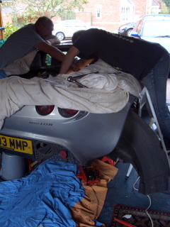
| + | [[Image:WorkingConditionsW.jpg|thumb|Working Conditions - N.B. Liner pulled back (step 4)]] | ||
4. Remove offside rear wheel arch liner. We had a issue with the rearmost lowest screw and so bent the flexible liner out of the way to access the engine mount bolts. | 4. Remove offside rear wheel arch liner. We had a issue with the rearmost lowest screw and so bent the flexible liner out of the way to access the engine mount bolts. | ||
| Line 52: | Line 53: | ||
6. Time for first cup of tea and bacon sandwiches | 6. Time for first cup of tea and bacon sandwiches | ||
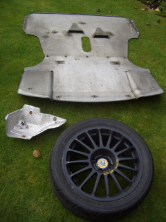
| + | [[Image:UndertrayHeatshieldAndORWheelW.jpg|thumb|Tray, heatshield, OR Wheel]] | ||
7. Remove manifold heat shield - three bolts. | 7. Remove manifold heat shield - three bolts. | ||
| Line 58: | Line 60: | ||
9. Crack off and put on loosely the bolts / nuts holding the downpipe to the cat and the cat to the exhaust. We had a major issue with one of the cat-exhaust bolts and had to chisel it off. | 9. Crack off and put on loosely the bolts / nuts holding the downpipe to the cat and the cat to the exhaust. We had a major issue with one of the cat-exhaust bolts and had to chisel it off. | ||
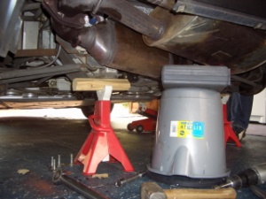
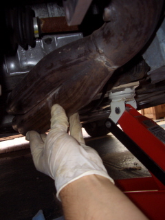
| + | [[Image:BackBoxAndCatSupportW.jpg|thumb|Stands, jack, and plastic bucket support!]] | ||
10. Remove CAT if possible. We left it in situ with the attached lambda sensor. Balanced on a makeshift bucket + toolbox platform. We did remove the back box though to provide more working space. | 10. Remove CAT if possible. We left it in situ with the attached lambda sensor. Balanced on a makeshift bucket + toolbox platform. We did remove the back box though to provide more working space. | ||
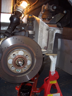
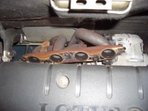
| − | 11. Remove two bolts holding engine mount to chassis - accessed via the offside rear wheel space. | + | [[Image:EngineMountW.jpg|thumb|Access to the engine mounting bolts]] |
| + | 11. Remove two bolts holding engine mount to chassis - accessed via the offside rear wheel space. These are the bolts that sit fore and aft of the engine mount and attach vertically down into the chassis longeron. Note that the bolts screw into some hard-to-access nuts inside the longeron extrusion. The nut to the fore of the engine mount is reasonably easy to access, whilst the aft one is more of a challenge and is best done by an assistant accessing it with a spanner via the car's boot. You'll need to use a spanner (open end) to hold the aft nut in place whilst undoing the associated bolt with a socket. For the bolt to the fore of the mount, you need to hold the bolt in place with a socket whilst undoing the nut underneath the longeron. Accessing the bolt to the fore of the engine mount will require a socket, a universal joint and a short extension bar. | ||
12. Remove the downpipe | 12. Remove the downpipe | ||
| Line 72: | Line 76: | ||
16. Unbolt the manifold from the head | 16. Unbolt the manifold from the head | ||
| + | [[Image:OldManifoldAlmostOutW.jpg|thumb|Unbolted and almost out]] | ||
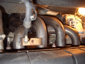
17. Remove manifold in two pieces through top and bottom of engine bay. | 17. Remove manifold in two pieces through top and bottom of engine bay. | ||
18. Soak manifold lambda sensor in Plusgas | 18. Soak manifold lambda sensor in Plusgas | ||
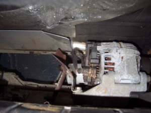
| + | [[Image:AlternatorHeatshieldW.jpg|thumb|Alternator heat shield, to left of alternator]] | ||
19. Take off alternator heat shield. This took an absolute age. Be careful not to round off the bolts. Small spanners and a gentle bit of persuasion with a lump hammer will get you there eventually, along with lots of Plusgas. | 19. Take off alternator heat shield. This took an absolute age. Be careful not to round off the bolts. Small spanners and a gentle bit of persuasion with a lump hammer will get you there eventually, along with lots of Plusgas. | ||
20. Oil filter off, catching 95% of the oil! Spend time mopping up the spillage until you have a clean worksurface once more. | 20. Oil filter off, catching 95% of the oil! Spend time mopping up the spillage until you have a clean worksurface once more. | ||
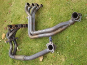
| + | [[Image:OldAndNewW.jpg|thumb|Compare old 'pig iron' mess, with sleek new manifold]] | ||
5hrs 30mins to this point. We now have everything off, its time to start to reconstruct with the new manifold. But more sandwiches and tea first... | 5hrs 30mins to this point. We now have everything off, its time to start to reconstruct with the new manifold. But more sandwiches and tea first... | ||
21. Looking from the rear of the car, slide the manifold in with it rotated 90 degrees anticlockwise | 21. Looking from the rear of the car, slide the manifold in with it rotated 90 degrees anticlockwise | ||
| − | offer the manifold up whilst jiggling the engine and pulling the manifold from above. Watch for the brake cable which runs exactly in the most inconvenient position. At times this task appears impossible. Just *how* can the manifold fit. Watch out for trapped fingers. Keep jiggling the engine block and rattling the manifold. Eventually it does pop through the impossible gap and into position. | + | offer the manifold up whilst jiggling the engine and pulling the manifold from above. Watch for the brake cable which runs exactly in the most inconvenient position. At times this task appears impossible. Just *how* can the manifold fit. Watch out for trapped fingers. Keep jiggling the engine block and rattling the manifold. Eventually it does pop through the impossible gap and into position. To re-iterate: it helps massively if you can have someone pulling the manifold upwards from above the engine bay at the same time as the person feeding the manifold under the engine. Brute force and ignorance are required, as the alternator heat-sheild mounting bracket on the manifold will foul against the transverse chassis rail at the base of the engine bay. |
| + | [[Image:HoldingManifoldInSituW.jpg|thumb|Keep manifold steady as it is being bolted to the head]] | ||
22. Fit manifold to head using the new gasket - with the "half hole end" fitting next to the water outlet from the head. Remember to use two washers between in each nut and the new manifold's flange (new flange is perhaps 5mm thinner than old flange). Be extremely careful not to cross thread the head bolts! | 22. Fit manifold to head using the new gasket - with the "half hole end" fitting next to the water outlet from the head. Remember to use two washers between in each nut and the new manifold's flange (new flange is perhaps 5mm thinner than old flange). Be extremely careful not to cross thread the head bolts! | ||
| + | [[Image:NewManifoldInW.jpg|thumb|What 'success' looks like :-)]] | ||
23. Alternator heat shield will need clipping with tin snips. Perhaps 5-6cm cut from the plate in order to accommodate the new manifold. I reused the one from Steve S2's car as it was a cast off from his Honda upgrade. I've didn't take a photo of the original and trimmed heatshields for reference. Sorry. | 23. Alternator heat shield will need clipping with tin snips. Perhaps 5-6cm cut from the plate in order to accommodate the new manifold. I reused the one from Steve S2's car as it was a cast off from his Honda upgrade. I've didn't take a photo of the original and trimmed heatshields for reference. Sorry. | ||
| Line 95: | Line 104: | ||
26. Refit engine mount bolts | 26. Refit engine mount bolts | ||
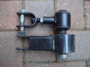
| + | [[Image:EngineBracketAlignmentNewAndOldW.jpg|thumb|Use the old to set the new length correctly]] | ||
27. Set the new adjustable engine steady bar to same length as the standard steady bar | 27. Set the new adjustable engine steady bar to same length as the standard steady bar | ||
| Line 113: | Line 123: | ||
35. Line up the undertray to guesstimate where extra sheet metal will have to be removed (approx 10cm x 15cm piece on the off-side rear of the existing hole. | 35. Line up the undertray to guesstimate where extra sheet metal will have to be removed (approx 10cm x 15cm piece on the off-side rear of the existing hole. | ||
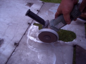
| − | 36. | + | [[Image:CuttingUndertrayW.jpg|thumb|Angle grinder on the undertray, showing rough pattern to cut.]] |
| + | 36. Use and angle grinder and snips to cut the sheet metal. | ||
37. Take the car for a spin. Listening for anything 'out of the ordinary'. I went for a 15 minute blast, getting up to 6000rpm - all OK. | 37. Take the car for a spin. Listening for anything 'out of the ordinary'. I went for a 15 minute blast, getting up to 6000rpm - all OK. | ||
| Line 134: | Line 145: | ||
== Conclusion == | == Conclusion == | ||
A valuable upgrade, definitely recommended for the price. Next step is to tie this into a cam change to extend the characteristics across the full range. For more info on just how a change in manifold design can make such a difference, follow [http://forums.seloc.org/viewthread.php?tid=136395] this link. | A valuable upgrade, definitely recommended for the price. Next step is to tie this into a cam change to extend the characteristics across the full range. For more info on just how a change in manifold design can make such a difference, follow [http://forums.seloc.org/viewthread.php?tid=136395] this link. | ||
| − | |||
| − | |||
| − | |||
== Credits == | == Credits == | ||
| − | Credit to SteveB, Steve S2 and BrianDrought who provided this comprehensive activity list based their own experiences. | + | Credit to SteveB, Steve S2 and BrianDrought who provided this comprehensive activity list based their own experiences. Special gold star to Steve S2 for travelling 200 miles to the grim north, not forgetting to bring his jack, axle stands and ready-cut alternator heat shield and then ruining his legs, back, arms and shoulders during the 11 hour fitting marathon. |
[[Category:Exhaust]] | [[Category:Exhaust]] | ||
[[Category:Lotus Elise]] | [[Category:Lotus Elise]] | ||
[[Category:S2]] | [[Category:S2]] | ||
Latest revision as of 10:12, 2 October 2007
Kit List
Head to manifold gasket
Cat to manifold gasket
Adjustable bottom engine mount
Piper 4-2-1 manifold
4L oil
Oil filter
Washers (lots - for use as spacers)
Tool List
Jack
Axle Stands
Spanners (open and ring), sockets: 10mm to 19mm
Plusgas seized bolt release spray
Latex gloves
Thread file (and perhaps Ford Pinto 2L spark plug)
Philips screwdriver
Ratchet wrenches - torque wrench size, mid range, and mini. For leverage and access.
Torch / inspection lamp
Oil tray / collector
Lump hammer
Bacon, HP Sauce, Bread, Tea, Kit-Kats, Beer, Coke
Method
1. Remove boot lid - disconnecting ariel and connectors. Note positioning and number of spacing washers.
2. Remove undertray (rear diffuser and mid section leaving them both as one piece)
3. Remove offside rear wheel
4. Remove offside rear wheel arch liner. We had a issue with the rearmost lowest screw and so bent the flexible liner out of the way to access the engine mount bolts.
5. Soak bolts / nuts holding the downpipe to the cat and the cat to the exhaust in Plusgas
6. Time for first cup of tea and bacon sandwiches
7. Remove manifold heat shield - three bolts.
8. Remove bolts holding the downpipe onto the manifold (from underneath the car with the engine still bolted in place)
9. Crack off and put on loosely the bolts / nuts holding the downpipe to the cat and the cat to the exhaust. We had a major issue with one of the cat-exhaust bolts and had to chisel it off.
10. Remove CAT if possible. We left it in situ with the attached lambda sensor. Balanced on a makeshift bucket + toolbox platform. We did remove the back box though to provide more working space.
11. Remove two bolts holding engine mount to chassis - accessed via the offside rear wheel space. These are the bolts that sit fore and aft of the engine mount and attach vertically down into the chassis longeron. Note that the bolts screw into some hard-to-access nuts inside the longeron extrusion. The nut to the fore of the engine mount is reasonably easy to access, whilst the aft one is more of a challenge and is best done by an assistant accessing it with a spanner via the car's boot. You'll need to use a spanner (open end) to hold the aft nut in place whilst undoing the associated bolt with a socket. For the bolt to the fore of the mount, you need to hold the bolt in place with a socket whilst undoing the nut underneath the longeron. Accessing the bolt to the fore of the engine mount will require a socket, a universal joint and a short extension bar.
12. Remove the downpipe
13. Within the engine bay, locate the loom to the manifold lambda sensor, and disconnect the lambda sensor.
14. Remove engine steady bar
15. Pull the engine rearwards - use the trolley jack to lift and shift the engine block. Using the sump as the contact point. 10cm square block of wood make this an easier task.
16. Unbolt the manifold from the head
17. Remove manifold in two pieces through top and bottom of engine bay.
18. Soak manifold lambda sensor in Plusgas
19. Take off alternator heat shield. This took an absolute age. Be careful not to round off the bolts. Small spanners and a gentle bit of persuasion with a lump hammer will get you there eventually, along with lots of Plusgas.
20. Oil filter off, catching 95% of the oil! Spend time mopping up the spillage until you have a clean worksurface once more.
5hrs 30mins to this point. We now have everything off, its time to start to reconstruct with the new manifold. But more sandwiches and tea first...
21. Looking from the rear of the car, slide the manifold in with it rotated 90 degrees anticlockwise offer the manifold up whilst jiggling the engine and pulling the manifold from above. Watch for the brake cable which runs exactly in the most inconvenient position. At times this task appears impossible. Just *how* can the manifold fit. Watch out for trapped fingers. Keep jiggling the engine block and rattling the manifold. Eventually it does pop through the impossible gap and into position. To re-iterate: it helps massively if you can have someone pulling the manifold upwards from above the engine bay at the same time as the person feeding the manifold under the engine. Brute force and ignorance are required, as the alternator heat-sheild mounting bracket on the manifold will foul against the transverse chassis rail at the base of the engine bay.
22. Fit manifold to head using the new gasket - with the "half hole end" fitting next to the water outlet from the head. Remember to use two washers between in each nut and the new manifold's flange (new flange is perhaps 5mm thinner than old flange). Be extremely careful not to cross thread the head bolts!
23. Alternator heat shield will need clipping with tin snips. Perhaps 5-6cm cut from the plate in order to accommodate the new manifold. I reused the one from Steve S2's car as it was a cast off from his Honda upgrade. I've didn't take a photo of the original and trimmed heatshields for reference. Sorry.
24. Fit alternator heat shield - again, this takes an age as there is almost no space to work in. Be careful to ensure bolts are aligned properly and no cross threading takes place.
25. Fit new oil filter
26. Refit engine mount bolts
27. Set the new adjustable engine steady bar to same length as the standard steady bar
28. Fit steady bar just with bolts
29. Check that manifold is sufficiently clear of the lower chassis transverse longeron. If not, shorten the adjustable steady bar. When all OK, torque up steady bar bolts and nuts.
30. Refit cat and back box - the exhaust exit pipes may need adjusting to suit the solid manifold.
31. Remove lambda sensor from old manifold. This could have been a tough job, but instead the sensor simply unscrewed with normal spanner usage! The expectation is that the lambda sensor will have siezed, but not in our case (135R with 20k miles)
32. File threads of lambda sensor with thread file, if threads are knackered then use a Ford Sierra 2.0 Pinto spark to rethread.
33. Plug the lambda sensor into position
34. Replace oil
35. Line up the undertray to guesstimate where extra sheet metal will have to be removed (approx 10cm x 15cm piece on the off-side rear of the existing hole.
36. Use and angle grinder and snips to cut the sheet metal.
37. Take the car for a spin. Listening for anything 'out of the ordinary'. I went for a 15 minute blast, getting up to 6000rpm - all OK.
38. Check and tighten bolts all around
39. Fix undertray back into position. Using washers to provide 5-10mm extra spacing for the central screws.
40. Wait a little longer for the manifold to have cooled down. Then attempt to replace the manifold heatshield. We had a major challenge here with the top most bolt. Perhaps due to engine block expansion due to heat? Finally in place, the bottom fixing bolt didn't make it though - it simply would not lock into position.
41. Replace boot lid and reconnect ariel.
42. Final cup of tea, and beer. Job well done.
5hrs 30mins to replace all the parts. 11 hours total.
Result
Much more low down torque, gives the car a whole new set of driving characteristics. Most notably when pulling away at lower speeds and gives a much better range for changing up and down. Much improved engine note - much 'cleaner', less boom and noise. Additionally, when slowing at speed the momentum is maintained much longer when throttling back, the engine note changes gentle and progressively. Haven't had the chance to experience differences at top end of the rev range. No difference in MPG / oil usage noted at this time.
Conclusion
A valuable upgrade, definitely recommended for the price. Next step is to tie this into a cam change to extend the characteristics across the full range. For more info on just how a change in manifold design can make such a difference, follow [1] this link.
Credits
Credit to SteveB, Steve S2 and BrianDrought who provided this comprehensive activity list based their own experiences. Special gold star to Steve S2 for travelling 200 miles to the grim north, not forgetting to bring his jack, axle stands and ready-cut alternator heat shield and then ruining his legs, back, arms and shoulders during the 11 hour fitting marathon.
