Difference between revisions of "Remote Boot Release for S2"
(→Wiring) |
(→Wiring) |
||
| Line 37: | Line 37: | ||
==Wiring== | ==Wiring== | ||
| − | The wiring required is | + | The wiring required is pretty simple, but it is pretty important you understand it because if you connect the wrong thing to the other wrong thing there is a good chance you can do some damage to either your car or yourself. If you don't understand what a relay is or does, read the [http://wiki.seloc.org/a/Remote_Boot_Release_for_S2#Random_Questions Random Questions] bit of this page. It will hopefully make a lot more sense then. |
| + | ===The circuits=== | ||
Two simple circuits need to be made - one with a button in it, the other with the solenoid in it. Parts of both of these circuits run through the relay. | Two simple circuits need to be made - one with a button in it, the other with the solenoid in it. Parts of both of these circuits run through the relay. | ||
If you can read a circuit diagram, you can probably make sense of this diagram. If you can't allow me to explain. | If you can read a circuit diagram, you can probably make sense of this diagram. If you can't allow me to explain. | ||
| − | Circuit 1 - "Button circuit" | + | ;Circuit 1 - "Button circuit" : This circuit runs from the 12v power supply (ie a live in the car somewhere), then through the button, then through the relay's coil, and finally to a ground in the car. |
| − | Circuit 2 - "Solenoid circuit" | + | ;Circuit 2 - "Solenoid circuit" : This circuit runs from the 12v power supply through the switching part of the relay, then through the solenoid, and finally to a ground in the car. |
What Circuit 1 does is when the button is pressed, it completes the circuit, and energises the coil in the relay. The energised coil closes the switch on the Circuit 2 part of the relay. Circuit 2 is now complete, so the solenoid is activated. Circuit 2 will remain complete until the button in Circuit 1 is released. | What Circuit 1 does is when the button is pressed, it completes the circuit, and energises the coil in the relay. The energised coil closes the switch on the Circuit 2 part of the relay. Circuit 2 is now complete, so the solenoid is activated. Circuit 2 will remain complete until the button in Circuit 1 is released. | ||
Revision as of 18:20, 11 April 2011
There is a kit available from Elise Parts for an S1 remote boot release. However the lock mechanism is mounted on the engine cover on an S2, not on the car, so to use this kit on an S2 it would require mounting the solenoid etc. on the engine cover its self. This isn't something I wanted to do, so I used a bit of ingenuity and put something together myself.
I (nor SELOC or anyone else) take any responsibility if you break your car as a result of following this guide. This is a guide, not a fool proof set of instructions, as such it should be used with this in mind. Be warned: it does involve some dicking about with the cars wiring, nothing major, but you have to get a 12v feed and an earth from somewhere. Remember to disconnect the battery before you start cutting cables!
These aren't "step by step" "cut this here, tape that there, prod this under that" instructions, some element of ingenuity is required to put the pieces together!
I did this mod on my '04 non-touring pack 111R.
Shopping List
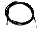
- 2m of bicycle brake cable (both inner & outer parts)
- 2x bicycle brake cable adjuster
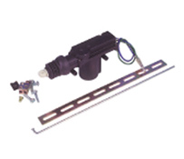
- Central Door Locking Solenoid - I used a YD79L from Maplins - it includes several things I used in this HowTo. Don't be tempted to buy a cheap kit from eBay that looks the same, I got one and it broke within 2 presses of the button
- A button
- A 4-pin 12v automotive relay - you need one which has an open switch when the coil is not energised, and closed when it is energised.
- Some male & female spade connectors
- Some cable ties
- Electrical insulation tape
- Double sided tape / velcro
- Some cable (I used about 6m or so of 7 amp cable, available from Halfrauds for about £3.79) The amount you will use/need will depend on where you choose to get the power/ground from, where you want to locate your button, the solenoid and the relay.
- Beers.
Tools
- Screwdrivers
- Cable cutters
- Stanley knife / cable stripper
- Pliers
- Drill & drill bits
- Allen keys
- Socket set
- Spanners
- T50 torx/star drive socket
Wiring
The wiring required is pretty simple, but it is pretty important you understand it because if you connect the wrong thing to the other wrong thing there is a good chance you can do some damage to either your car or yourself. If you don't understand what a relay is or does, read the Random Questions bit of this page. It will hopefully make a lot more sense then.
The circuits
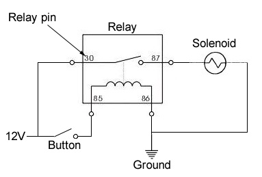
Two simple circuits need to be made - one with a button in it, the other with the solenoid in it. Parts of both of these circuits run through the relay.
If you can read a circuit diagram, you can probably make sense of this diagram. If you can't allow me to explain.
- Circuit 1 - "Button circuit"
- This circuit runs from the 12v power supply (ie a live in the car somewhere), then through the button, then through the relay's coil, and finally to a ground in the car.
- Circuit 2 - "Solenoid circuit"
- This circuit runs from the 12v power supply through the switching part of the relay, then through the solenoid, and finally to a ground in the car.
What Circuit 1 does is when the button is pressed, it completes the circuit, and energises the coil in the relay. The energised coil closes the switch on the Circuit 2 part of the relay. Circuit 2 is now complete, so the solenoid is activated. Circuit 2 will remain complete until the button in Circuit 1 is released.
The numbers in the diagram above in the relay (the box at the top) correspond to the pins on the relay. If your relay does not have the same numbers on the pins, normally a small circuit diagram on the side of the relay will describe what each pin refers to. For now, I am going to assume you have a relay with the same numbers on it.
It is entirely up to you how you wire this up and where you wire it up from.
How to do it
- Remove both seats.
- The passenger seat has 4 allen bolts. The drivers seat has 2 hex bolts & two allen bots.
- Note: there is a small seat runner stop on the drivers seat. Don't loose it!
- Undo the seat and top mounts of both the seatbelts.
- Undo the seatbelts from the side of the seats (requires a 17mm spanner).
- Unclip the plastic covers over the top seatbelt mounts.
- Unbolt top mount of the seatbelt from the rollover hoop (requires a T50 torx/star drive socket and a BIG socket wrench, as it is bloody tight!).
- Remove the centre console storage pocket.
- Undo the screw at the bottom of the pocket from the top.
- Then undo the two screws you can see holding the lower part in.
- Carefully lift it out the way, and disconnect the plug on the back of the auxiliary power socket.
- Remove the speakers
- Unclip the cover over the speaker (if you have any), you may need a flat-head screwdriver to prize it off.
- Undo the securing screws holding the speaker in and carefully remove the speaker from the housing making sure you don't snag the speaker wires.
- Disconnect the wires to the speakers.
- Remove the bulk head covering
- Undo the 5 (?) screws / plugs securing the cover to the bulkhead. These may need persuading with a flat-head screwdriver to come out.
- The whole cover needs to be "manipulated", shall I say, to get it in/out of the car!
- Start at the bottom on one side near the seatbelt reels. You need to carefully bend the cover out from behind the roll-over bar cover.
- Once the bottom is out, work the top out in a similar way. It does need a bit of restrained brute force, but it will come out.
- Disconnect the connector on light in the middle of the panel before trying to remove it from the car entirely.
NOTE: My car doesn't have insulation behind the bulk head covering as it isn't a "touring" model.
Random Questions
- What is a relay?
- A relay is a method way of using a low current/voltage switch to safely connect/disconnect a higher current/voltage circuit, useful when switching motors etc on and off.
- How does a relay work?
- Very simply - a low voltage circuit is used to provide power to a electromagnetic coil which, when active, will connect another higher voltage circuit.
- Why a relay?
- You need a relay because you will burn the switch out with the current required to power the solenoid. If you put a switch into the low voltage coil circuit, by turning the switch on, you can control if the coil is on or not (thus connecting or disconnecting the high voltage circuit).


