Difference between revisions of "Pedal Box Refurbishment"
| Line 77: | Line 77: | ||
I found this to be the best order of working…. | I found this to be the best order of working…. | ||
| − | ==== | + | ====Getting the bloody thing out==== |
| − | + | *Disconnect battery | |
| − | + | **I have a master battery cut-out switch, you will probably need to physically disconnect the positive terminal | |
| − | + | **'''TAKE CARE TO RECONNECT TO THE CORRECT TERMINAL WHEN YOU PUT IT BACK TOGETHER OR YOUR ECU MAY TOAST ITSELF''' | |
| − | + | *Remove Driver’s seat | |
| − | + | **Four Allen bolts – front two easy with a cut down Allen key, rear two easy with an Allen key socket and multiple extension bars | |
[[Image:Pedal_Box_03.JPG|Driver's Seat Removed]] | [[Image:Pedal_Box_03.JPG|Driver's Seat Removed]] | ||
| + | |||
| + | |||
| + | |||
| + | *Remove Steering column shroud | ||
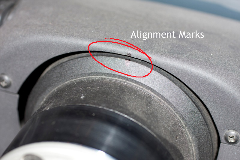
| + | **Mark the steering column shroud and wheel at top dead centre - you’ll need to align things back again on reassembly so that your steering wheel isn’t at a crazy angle | ||
| + | **Undo 4 x small self-tappers holding upper shroud to lower shroud | ||
| + | **Undo 3 x large self tappers holding lower shroud to column (underneath lower shroud) | ||
| + | **Remove trip meter reset/dash light dimming button | ||
| + | **Put lower shroud on the dashboard – the touch key cable is just long enough | ||
| + | |||
| + | [[Image:Pedal_Box_09_annotated.jpg|Steering boss and shroud marked]] | ||
| + | |||
| + | |||
| + | *Remove Stack | ||
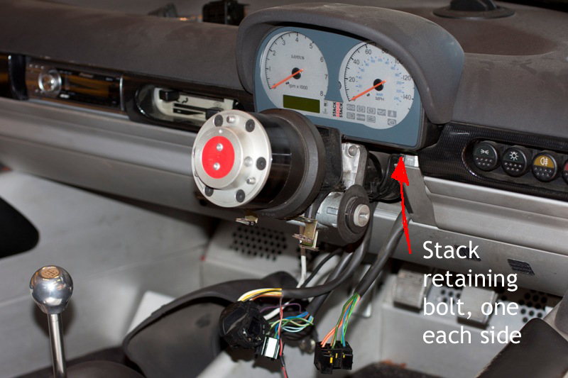
| + | **Undo two bolts visible to either side of the steering column holding the stack onto the main steering column mount | ||
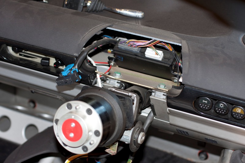
| + | **Disconnect the single stack connector – there is a latch that you need to hold down and it’s quite stiff | ||
| + | |||
| + | [[Image:Pedal_Box_10_annotated.jpg|Stack Fixing Bolts]] | ||
| + | [[Image:Pedal_Box_11.JPG|Stack removed]] | ||
Revision as of 11:19, 22 June 2011
SELOC how-to: Elise S1 Pedal Box Refurbishment
Firstly, Don’t. Just Don’t. Take your car and a big bundle of cash to your favourite spanner men and let them do it. Trust me on this. You REALLY don’t want to do this job. Not in a million years.
Anyone past the first paragraph will fall into one of two categories:
1. Terminally tight as a gnat’s chuff, or
2. The sort of person who has whips, nipple clamps and gimp suits in the cellar
Either way, I take my hat off to you - you are about to spend between 12 and 18 hours contorted into various unlikely positions and swearing profusely at your little plastic sports car, or “Yellow Piece of Shit”, as mine is now known.
First, you’ll need the bits. The official Lotus parts are these:
This list of parts will enable you to put the pedal box back to factory fresh condition, assuming that your brake trunnion is in good condition (these appear to be good for well over 100k miles, based on anecdotal evidence). If you need the brake trunnion, it’s part number A111J0039F.
I decided that the original arrangement, particularly on the throttle pedal, could do with improvement, so designed an alternative that hopefully will last longer and does immediately improve pedal feel.
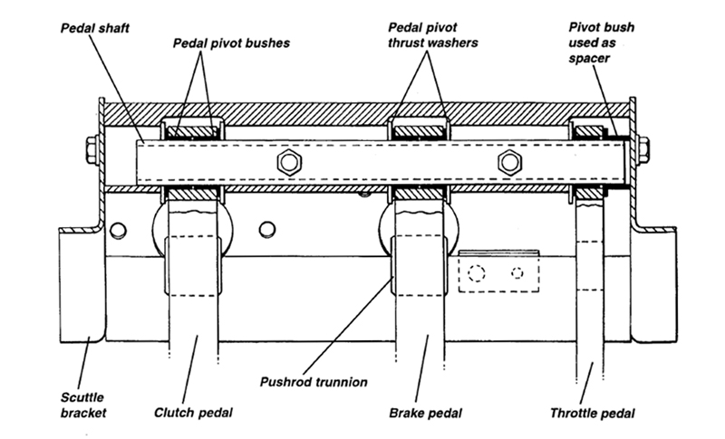
The problem with the original Lotus Pedal Arrangement
In the above diagram, you can see that Lotus used two standard pivot bearings and a single thrust washer to locate the throttle pedal. I see three issues with this:
1.Support for the right-hand face of the pedal is wholly dependent on the fit of the pivot bearing being used as a spacer
2.The pivot bearings are a running fit on the shaft, and the frictional forces involved means that the bearing will rotate with the pedal when it’s moved
3.The net bearing area where the “spacer” bush meets the scuttle bracket is tiny – these bearings are pretty thin – so the wear rate at that end of the bearing is likely to be large.
With a high wear rate, and the feel of the pedal determined by that fit, I felt that a different arrangement was called for to future proof my pedal box. After all, I never intend to do this job again :)
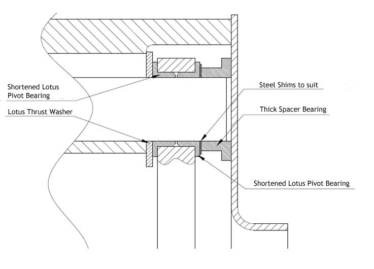
My solution to the problem
In essence, I shortened both bearings that would normally be used so that they would fit the pedal as per the other pedals, then found a suitable larger bush to fit and use as a spacer. Because I would be manually modifying these parts, I needed some method to get a good close running fit, so found some suitable shim washers in varying thicknesses to take up the slack. I ended up using the same shim washers to take out most of the axial play in the other pedals too.
Net result is that both shoulders of the throttle pedal are properly supported, and there is a much larger bearing area on the pedal/spacer interface. Should last much longer!
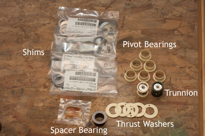
The parts list I ended up using is below:
I managed to get the thrust washers from igus who very usefully have a free sample ordering option. I chanced my arm and asked for 5 as free samples. You have to put in some info and rationale – I said that I am designing a modular lightweight automotive pedal box system (not a million miles from the truth) and they showed up the next day! For those of you with a higher sense of ethics than me, they can be bought from the same source and will cost you a total of £18.35 for 5, which is still cheaper than Lotus. As far as I can tell, they are exactly the same part. In fact, the pivot bearings seem to be exactly the same as igus part number JFM-2023-11. These are cheaper from Lotus though.
The thick spacer bearing and shim washers came from ondrives. These parts took a little longer to arrive, around two weeks. Plan accordingly if you’re not blagging shims from me :)
In fairness, I did also buy two additional bags of shims – 0.5mm and 1mm thick because I had no idea how much clearance I’d need to take up. I didn’t use any of them so you’ll most likely only need the 0.1mm and 0.2mm shims.
Of course, I now have a bag of 94 0.1mm shims and a bag of 98 0.2mm shims, so if anyone is interested I can send you a few - just u2u me :)
How to spend 18 hours of your life swearing at your car
So – here’s the interesting bit. First, check that you have all the bits you’ll need:
(Or use the Lotus parts, which will look identical except for the spacer bush and shims. I only used the trunnion with the pale bushes in the end because I decided against using a compressible bush trunnion in the brake pedal)
I found this to be the best order of working….
Getting the bloody thing out
- Disconnect battery
- I have a master battery cut-out switch, you will probably need to physically disconnect the positive terminal
- TAKE CARE TO RECONNECT TO THE CORRECT TERMINAL WHEN YOU PUT IT BACK TOGETHER OR YOUR ECU MAY TOAST ITSELF
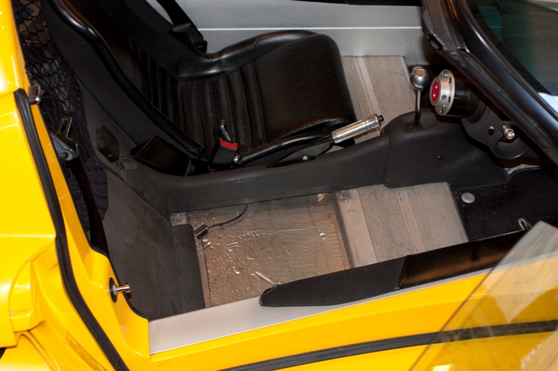
- Remove Driver’s seat
- Four Allen bolts – front two easy with a cut down Allen key, rear two easy with an Allen key socket and multiple extension bars
- Remove Steering column shroud
- Mark the steering column shroud and wheel at top dead centre - you’ll need to align things back again on reassembly so that your steering wheel isn’t at a crazy angle
- Undo 4 x small self-tappers holding upper shroud to lower shroud
- Undo 3 x large self tappers holding lower shroud to column (underneath lower shroud)
- Remove trip meter reset/dash light dimming button
- Put lower shroud on the dashboard – the touch key cable is just long enough
- Remove Stack
- Undo two bolts visible to either side of the steering column holding the stack onto the main steering column mount
- Disconnect the single stack connector – there is a latch that you need to hold down and it’s quite stiff

