Difference between revisions of "Cambelt"
| Line 82: | Line 82: | ||
5. Remove RHS rear wheel arch liner | 5. Remove RHS rear wheel arch liner | ||
| − | 6. You may wish to remove the brake disc on the RHS rear wheel to allow greater access into the wheel arch when working (it is not necessary to do this | + | 6. You may wish to remove the brake disc on the RHS rear wheel to allow greater access into the wheel arch when working (it is not necessary to do this) |
[[File:Cambelt1.jpg|thumb|none|View with Liner Out]] | [[File:Cambelt1.jpg|thumb|none|View with Liner Out]] | ||
| Line 112: | Line 112: | ||
14. Remove the lower cam cover | 14. Remove the lower cam cover | ||
| − | 15. Before removing the cam belt the engine has to be positioned with No1 Piston at Top Dead Centre (TDC). Replace the crank bolt (only) and hand tighten. | + | 15. Before moving onto removing the cam belt the engine has to be positioned with No1 Piston at Top Dead Centre (TDC). Replace the crank bolt (only) and hand tighten. |
| − | Its worth highlighting the camshaft sprocket marks, the crankshaft sprocket marks and the engine block mark with some Tippex (or white paint) for ease of viewing | + | Its worth highlighting the camshaft sprocket alignment marks, the crankshaft sprocket alignment marks and the engine block alignment mark with some Tippex (or white paint) for ease of viewing |
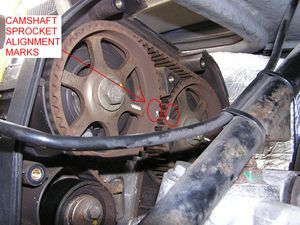
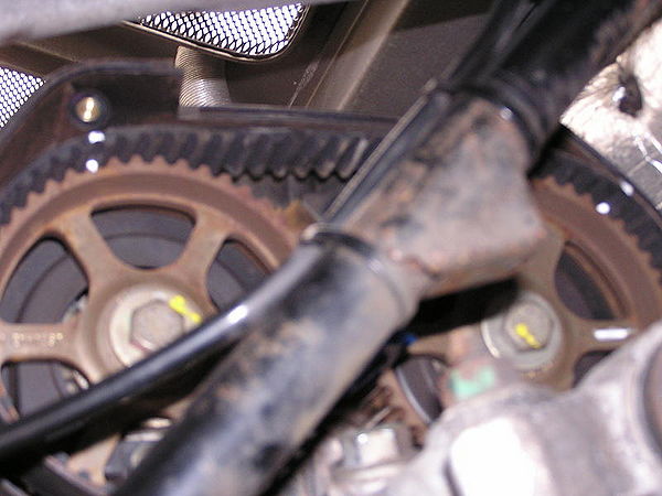
[[File:Cambelt5.jpg|thumb|none|Camshaft Alignment Marks]] | [[File:Cambelt5.jpg|thumb|none|Camshaft Alignment Marks]] | ||
| Line 120: | Line 120: | ||
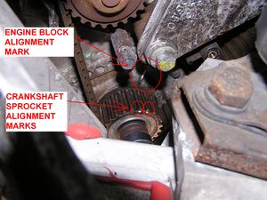
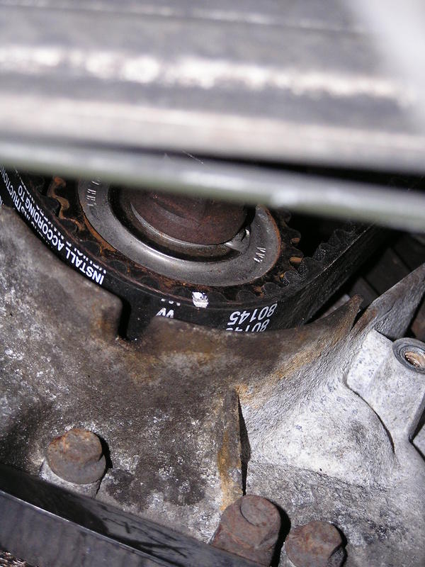
[[File:Cambelt6.jpg|thumb|none|Crankshaft and Block Alignment Marks]] | [[File:Cambelt6.jpg|thumb|none|Crankshaft and Block Alignment Marks]] | ||
| − | 16. Remove the screwdriver/allen key from the flywheel teeth, and with the car out of gear. Turn the engine using a rachet/spanner on the crank bolt (only ever turn clockwise), until the camshaft and crank shaft alignment mark line up as above. Camshaft marks | + | 16. Remove the screwdriver/allen key from the flywheel teeth, and with the car out of gear. Turn the engine using a rachet/spanner on the crank bolt (only ever turn clockwise), until the camshaft and crank shaft alignment mark line up as above. Camshaft marks should face each other in a line with the centre bolts of each shaft, crank marks should straddle the block mark. |
| − | 17. Replace the screwdriver or allen key in the flywheel | + | 17. Replace the screwdriver or allen key in the flywheel and place the camshaft locking tool into place |
[[File:Cambelt7.jpg|thumb|none|Cam Locking Tool]] | [[File:Cambelt7.jpg|thumb|none|Cam Locking Tool]] | ||
| − | 18. | + | 18. Mark the old belt/sprockets at both cams and on the crank. When the old belt is off, transfer these marks to the new belt. When fitting the new, the marks will ensure it is not out by a tooth anywhere along its length (the K series will run without damage when the belt is out by a tooth either way but not very well!!). |
[[File:Cambelt8.jpg|thumb|none|Belt to Sprocket Double Check] | [[File:Cambelt8.jpg|thumb|none|Belt to Sprocket Double Check] | ||
Revision as of 20:26, 6 September 2011
PLEASE ADD INFORMATION, WORK IN PROGRESS
Part numbers
For auto tensioner:
Rover pt no, LHN100560
Gates pt no. 5497XS
Piper pt no TBP33
For manual tensioner:
Rover pt no. LHN100390
Gates pt no. 5416XS
Piper pt no. TBP17 wide
Cambelt
Lotus have amended the original schedule and now recommend changing cam belts at least every four years rather than the original six, this will often mean services can become "A+belts", "B+belts", or "C-belts" depending on age and mileage and you will need to track the age of the cambelt separately from the normal service history.
Extract from Group Lotus Aftersales bulletin ...
The synthetic cam belt used on Rover powertrain Elise models is subject to age, as well as usage degradation, and will be adversely affected by any contamination with oil or coolant. In order to bring cam-belt time servicing in line with current Rover recommendations the Service Schedule for all Rover powertrain Elise models was revised in October 2003 to stipulate a cam belt replacement time interval of 4 years (54,000miles/90,000km), with an inspection every 2 years (27,000miles/45,000km). For 340R/Sport 160/Exige models, the corresponding distance intervals are 36,000miles/60,000km, and 18,000miles/30,000km.
Tensioner
PLEASE ADD INFORMATION
Auto or Manual
Changing the Cambelt (Auto Tensioner inc Water Pump)
It is much easier to change the cambelt with the rear clam off but this is not necessary and access through the drivers rear wheel arch with the liner removed is still excellent compared to most 16v engines.
Instructions are for a "clam on" change
The rear of the car needs to be a high as possible at the rear to allow access to loosen and torque up the crank bolt (210Nm is tight)
Tools Required
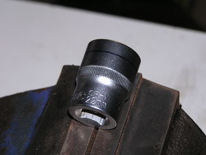
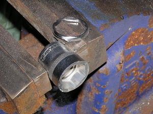
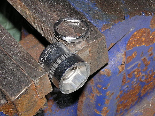
You will require a cut down 22mm socket to fit in the limited space between the crank pulley and the chassis (a 6 sided socket is stronger than a 12sided. Silverline do one for a couple of ££'s from Amazon)
You will also need a
. 1/2" breaker bar to loosen the crank bolt. As long as possible (don't try and use a ratchet handle, you'll break it and get a hernia to boot)
. a torque wrench capable of operating up to 210Nm (with a slim head if possible)
. A Rover K Series camshaft locking tool
Method
1. Run the rear of the car up on ramps if you have them and remove the rear undertray and diffuser. Loosen the RHS rear wheel nuts while the weight of the car is still on the wheel
2. Remove the spark plugs (this will allow the engine to be turned over much easier using the crank bolt as required below
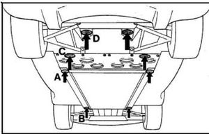
3. Jack up the RHS of car higher still and place axle stands at the B and C positions in the daigram (if you don't have ramps then jack and support with axle stands in stages, as the tilt on the car can easily cause it to slip off a jack on it own)
.
Try and get the car high enough that you can kneel with your head inside the rear wheel arch (when the liner is out) as this is a comfortable working position allowing you to reach into the engine bay through the arch
4. Move the ramp out of your way and remove RHS rear wheel
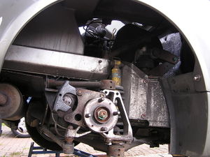
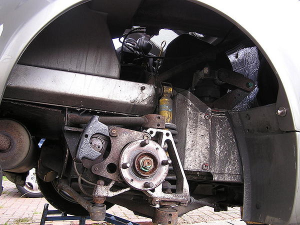
5. Remove RHS rear wheel arch liner
6. You may wish to remove the brake disc on the RHS rear wheel to allow greater access into the wheel arch when working (it is not necessary to do this)
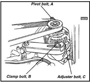
7. Loosen the pivot bolt and clamp bolt on the alternator
8. Loosen the adjuster bolt to move the alternator towards the engine and provide slack on the the belt. (If you intend to refit the existing alternator belt, before undoing the adjuster bolt, mark the position of the clamp bolt on the slotted bracket, so that you know exactly where to tighten the belt up to on reassembly)
9. Remove the alternator belt
10. Unbolt the upper cam belt cover and maneuver it upwards and out via the the engine bay (the cover to clam clearance is tight, but it will come out with minimum force if jiggled about a bit)
Unsure that you do not loose the rubber seal that press fits onto the bottom edge of the upper cover
11. Before loosening the crank bolt place a suitably sized screwdriver or allen key in the visible flywheel ring gear next to the RHS driveshaft to prevent the engine rotating (I found an allen key much less likely to slip)
12. From under the car and using the breaker bar with the cut down socket, loosen the crank bolt (you are likely to have to brace your knees/feet against the underside to gain enough purchase to undo the bolt)
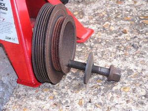
13. Remove the crank bolt, the large washer (note orientation) and then the crank pulley
14. Remove the lower cam cover
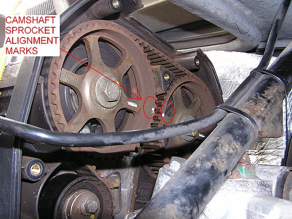
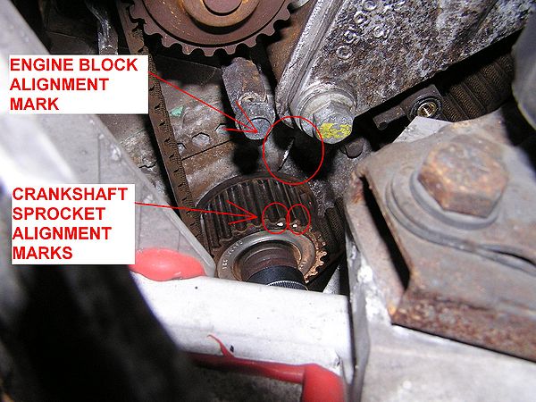
15. Before moving onto removing the cam belt the engine has to be positioned with No1 Piston at Top Dead Centre (TDC). Replace the crank bolt (only) and hand tighten.
Its worth highlighting the camshaft sprocket alignment marks, the crankshaft sprocket alignment marks and the engine block alignment mark with some Tippex (or white paint) for ease of viewing
16. Remove the screwdriver/allen key from the flywheel teeth, and with the car out of gear. Turn the engine using a rachet/spanner on the crank bolt (only ever turn clockwise), until the camshaft and crank shaft alignment mark line up as above. Camshaft marks should face each other in a line with the centre bolts of each shaft, crank marks should straddle the block mark.
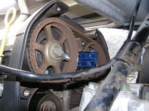
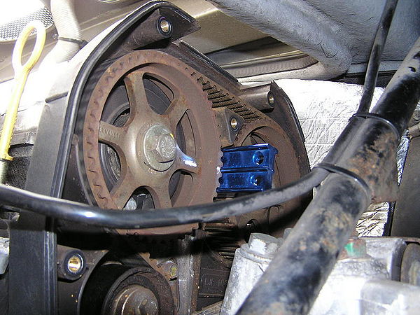
17. Replace the screwdriver or allen key in the flywheel and place the camshaft locking tool into place
18. Mark the old belt/sprockets at both cams and on the crank. When the old belt is off, transfer these marks to the new belt. When fitting the new, the marks will ensure it is not out by a tooth anywhere along its length (the K series will run without damage when the belt is out by a tooth either way but not very well!!).
[[File:Cambelt8.jpg|thumb|none|Belt to Sprocket Double Check]
19.
XXXXXXXXXXXXXX
Place a trolley jack under the right side of the engine and support the bottom of the engine using a small block of wood
8. Loosen and remove the 2 engine mounting bolts on the right hand engine mount. The engine should now be supported on the jack.
9. Very carefully lower the trolley jack so the engine drops about a maximum of one inch. This will enable access to the crankshaft pulley bolt and facilitate fitting the new cambelt through the gap now created.
OR
You could do the following (Thanks to Dave Andrews for the tip): You do not need to support the engine or remove both engine mounting bolts. It is perfectly possible and easier to remove one bolt at a time on the engine mount and weave the belt in between the bolts. Slacken both so that the mount drops by 12mm or so, remove the left hand bolt and push the belt in the gap between mountings. Replace the left hand bolt and tighten to where it was (I.E. 12mm gap), then remove the right hand bolt and push the belt the rest of the way through the gap, then do up the bolts. It's faster and requires no trolley jack under the sump.
10. Use a long flatbladed screwdriver to lock the crankshaft by shoving a screwdriver into the ring gear. This is visible just in front of the right-hand driveshaft at the gearbox end.
11. Use a 22mm socket to loosen the crankshaft pulley. You may need to shorten a 22mm socket to make access easier as space is a bit cramped.
12. Remove the crankshaft pulley.
13. Remove the plastic cambelt covers (top and bottom)
14. Checking the timing and fitting the cambelt. The following is only an outline guide for reference and I would suggest that you read the 'Service Manual' for detailed instructions before doing this.
(i) There are timing marks on the camshaft pulleys and crank timing gear pulley
(ii) Line up the two arrows on the camshaft pulleys (as per the manual). Do this by refitting the crankshaft bolt (but not the pulley). You can now turn the camshafts by turning the crankshaft using a socket.
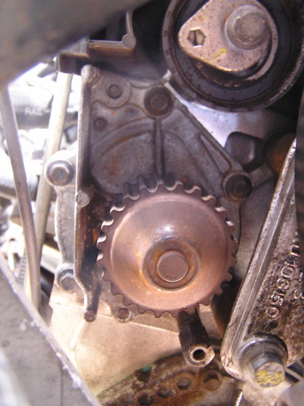
(iii) Check the position of the crank timing gear pulley as follows: Look down at the teeth on the gear at end of the crankshaft and you should see two dimples. If the timing is right these should be on either side of a vertical line cast on the engine block (flange on oil pump). These tell you that the crank is in the right place. If your old timing was out you might end up with the cams right and the crank wrong or vice versa. The most important thing is to park the crank in the right place. Now whip off the timing belt and line up the cam shafts properly (you're safe to do this only because you parked the crank in the right place - otherwise you risk piston/valve contact!) (i.e. with the arrows pointing straight across). Use a camshaft locking tool to lock the camshafts.
(iv) Now put on the new belt and adjust the tensioner. Turn the engine over two complete revolutions clockwise. Recheck all the timing marks end up in the right place. Assuming all is well, remove the 22mm bolt, and rebuild everything.
15. Refit in the reverse order following the torque specifications in the manual - about 205Nm for the crankshaft pulley, 45Nm for the cambelt tensioner pulley allen bolt and 10Nm for the tensioner backplate screw.
(Alternative methods used to lock the crank include having the car in gear and an assistant press on the brakes VERY hard. Seems OK to unlock the cran bolt but when doing up any slipage will through out the timing !!!)
NOTE There have been a small number if instances reported where the cambelt centre tensioner bolt has become seized to the block through corrosion/overzealous tightening or the use of thread lock. Before stripping the engine to find this may be the case and you now have a car that is incapable of being driven to a garage/mechanic, you can check the tensioner bolt will loosen. This is possible by removing the upper cam belt cover before all else and trying to move the bolt a quarter turn. If it moves, tighten it back up and follow the normal procedure above
Useful video:
http://www.mgf.ultimatemg.com/group2/engines/index.htm
Picture Guide
From the thread here: http://forums.seloc.org/viewthread.php?tid=314945&page=1#pid5349364
1. Loads of space when you raise the rear up on axle stands. I could work on my knees with my head and shoulders inside the arch. Best access I've had in a car to change a cambelt. You can do it all by sight rather than touch. All photos were taken with me under the arch as well.
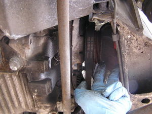
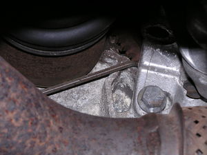
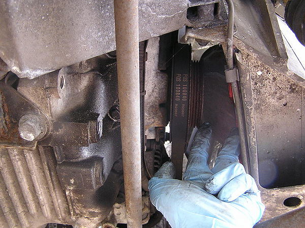
2. Space between crank pulley and car looking directly up from beneath.
3. Top cover off
4. Socket cut down with an angle grinder. I could now get this on the crank bolt with a breaker bar to undo but did have to undo the engine mounting bolts about 2-3cm to drop the engine slightly to allow my torque wrench in to do it back up (210Nm).
5. Aligning cam and crank sprockets.
6. Lock cams.
7. Mark old belt/sprockets at both cams and on the crank - I used typist correction fluid. I transferred these marks to the new belt and that way I knew when fitting the new one I was not out by a tooth anywhere (the car will actually run with out damage when out by a tooth either way but obviously its not going to run well!!).
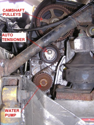
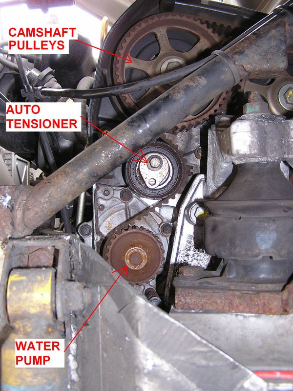
8. Old water pump in situ, which I replaced. Again access, I think, is great.
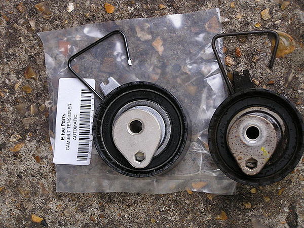
9. New auto tensioner. Leave the centre bolt loose to allow the tensioner to wobble a bit giving you more leeway to slide on the cam belt.
10. New belt going with marks (sorry a bit blurry).
Follow the destructions for tensioning the belt, replace lost coolant, bleed and bingo...
The hardest part was getting the top cam cover up and out of the engine bay and back in again when finished, but a bit of wiggling and it just all of a sudden fits through the gap.
Tools
PLEASE ADD INFORMATION
See Also
PLEASE ADD INFORMATION
