Difference between revisions of "Gauges"
m (added categories) |
m |
||
| (6 intermediate revisions by 3 users not shown) | |||
| Line 2: | Line 2: | ||
| − | I got my Gauges from Demon Tweaks. A nice STACK Anologue Gauge for Oil Temp (Electrical Sensor) and | + | I got my Gauges from Demon Tweaks. A nice STACK Anologue Gauge for Oil Temp (Electrical Sensor) and mechanical Boost gauge for the SC (Barry boy style) |
I decided to Install the Gauges into the center air vents. This is because i don't use them and the 52MM gauges will fit quite nicely leaving an OEM look to them rather than those Aluminium Mounting cages (Your Preference) | I decided to Install the Gauges into the center air vents. This is because i don't use them and the 52MM gauges will fit quite nicely leaving an OEM look to them rather than those Aluminium Mounting cages (Your Preference) | ||
| Line 16: | Line 16: | ||
These (on my car) are located here: | These (on my car) are located here: | ||
| − | + | [[Image:Gau1.JPG|thumb|left|Click to enlarge]] | |
| + | {{clr}} | ||
| + | |||
With the Facia removed you can either splice into the loom or as i have done, remove the circuit board (4 Screws) and solder the 3 connections into the board. If you are handy with a solder iron this is easy to do. | With the Facia removed you can either splice into the loom or as i have done, remove the circuit board (4 Screws) and solder the 3 connections into the board. If you are handy with a solder iron this is easy to do. | ||
| Line 22: | Line 24: | ||
Note the orientation of the board: | Note the orientation of the board: | ||
| − | + | [[Image:Gau2.JPG|thumb|left|Click to enlarge]] | |
| + | {{clr}} | ||
| + | |||
I also put Clear silicone over the solder connections to stop any cross connections being made on the aluminium mounting bracket when the board is screwed back into place. | I also put Clear silicone over the solder connections to stop any cross connections being made on the aluminium mounting bracket when the board is screwed back into place. | ||
| + | |||
| + | Please note that most silicone sealants release acetic acid which is corrosive to PCBs. Make sure the adhesive/sealant used is suitable e.g. Dow Corning 744, Loctite 444 or hot glue (if you like to make a mess). | ||
Now back in place you can see the 3 new wires poking out: | Now back in place you can see the 3 new wires poking out: | ||
| − | + | [[Image:Gau3.JPG|thumb|left|Click to enlarge]] | |
| − | + | {{clr}} | |
| − | |||
Gauges: | Gauges: | ||
| Line 42: | Line 47: | ||
Your left with 2 peices: | Your left with 2 peices: | ||
| − | [ | + | [[Image:Gau4.JPG|thumb|left|Click to enlarge]] |
| + | {{clr}} | ||
| + | |||
I used clear silicone to sick the gauge into the vent surround (Some filing was needed of notches inside) | I used clear silicone to sick the gauge into the vent surround (Some filing was needed of notches inside) | ||
| − | + | [[Image:Gau5.JPG|thumb|left|Click to enlarge]] | |
| + | {{clr}} | ||
| + | |||
Once this is dry (over night) i then stuck the vent face and gauge into the main air vent sleeve. | Once this is dry (over night) i then stuck the vent face and gauge into the main air vent sleeve. | ||
| − | + | [[Image:Gau6.JPG|thumb|left|Click to enlarge]] | |
| + | {{clr}} | ||
| + | [[Image:Gau7.JPG|thumb|left|Click to enlarge]] | ||
| + | {{clr}} | ||
| − | |||
| Line 66: | Line 77: | ||
Remembering the vent sleeve has to fit back into the air vent you need to have enough "slack" on the wires for this. I also put the wires through the holes in the side of the sleeve left from where the vent flaps :o pivoted. | Remembering the vent sleeve has to fit back into the air vent you need to have enough "slack" on the wires for this. I also put the wires through the holes in the side of the sleeve left from where the vent flaps :o pivoted. | ||
| − | + | [[Image:Gau8.JPG|thumb|left|Click to enlarge]] | |
| + | {{clr}} | ||
| + | |||
Not an amazing finish at the back but the front is what matters. | Not an amazing finish at the back but the front is what matters. | ||
| − | + | [[Image:Gau9.JPG|thumb|left|Click to enlarge]] | |
| + | {{clr}} | ||
| + | |||
Hoepfully others find the wire locations useful. | Hoepfully others find the wire locations useful. | ||
| + | |||
| + | Fan blower (With air con) Connector positions. Starting with the bottom (single) spade connector and working ANTi-Clock wise. | ||
| + | {{clr}} | ||
| + | Green grey (bottom connector) | ||
| + | {{clr}} | ||
| + | green blue | ||
| + | {{clr}} | ||
| + | thin green blue | ||
| + | {{clr}} | ||
| + | green | ||
| + | {{clr}} | ||
| + | green yellow | ||
| + | |||
[[Category:Lotus Elise]] | [[Category:Lotus Elise]] | ||
[[Category:S2]] | [[Category:S2]] | ||
[[Category:Electrical]] | [[Category:Electrical]] | ||
Latest revision as of 20:02, 24 May 2010
This guide should be fine for S2 drivers - maybe just Yota engine but as a point this is a guide so it's not my fault if you blow fuses! ;)
I got my Gauges from Demon Tweaks. A nice STACK Anologue Gauge for Oil Temp (Electrical Sensor) and mechanical Boost gauge for the SC (Barry boy style)
I decided to Install the Gauges into the center air vents. This is because i don't use them and the 52MM gauges will fit quite nicely leaving an OEM look to them rather than those Aluminium Mounting cages (Your Preference)
First remove the 2 screws (one either side) of the heater/blower controls. Now pull the peice forward, the top is clipped in and it will pop out.
Disconnect the wires at the back of the heater/blower and make sure you don't mix up the ones that connect to the fan speed control!
Wiring:
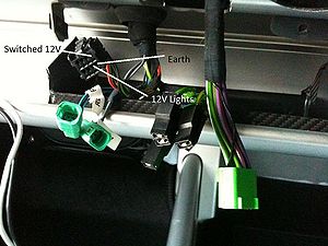
I decided to use the Switch 12v and 12V Light connections that form part of the circuit board feed to the heater/blower controls.
These (on my car) are located here:
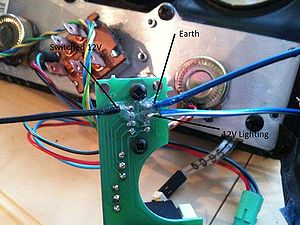
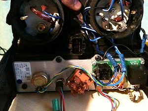
With the Facia removed you can either splice into the loom or as i have done, remove the circuit board (4 Screws) and solder the 3 connections into the board. If you are handy with a solder iron this is easy to do.
Note the orientation of the board:
I also put Clear silicone over the solder connections to stop any cross connections being made on the aluminium mounting bracket when the board is screwed back into place.
Please note that most silicone sealants release acetic acid which is corrosive to PCBs. Make sure the adhesive/sealant used is suitable e.g. Dow Corning 744, Loctite 444 or hot glue (if you like to make a mess).
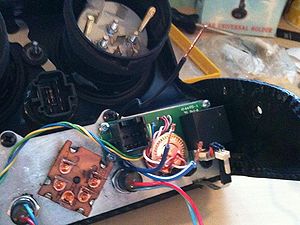
Now back in place you can see the 3 new wires poking out:
Gauges:
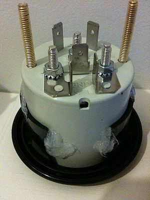
I actually did these first (you can see them in a few pictures)
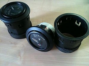
1:Remoe the air vent from the facia. 2:Remove the "flaps" if you flex the vent these come out easier, Clean and remove the lube/grease and dirt. 3:Using a screwdriver ease the face off the remaining plastic section away from the vent flaps.:o
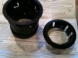
Your left with 2 peices:
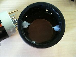
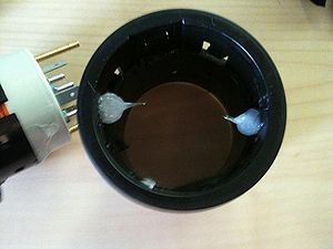
I used clear silicone to sick the gauge into the vent surround (Some filing was needed of notches inside)
Once this is dry (over night) i then stuck the vent face and gauge into the main air vent sleeve.
NOTE: The vent sleeve is NOTCHED make sure you have the notches in the correct orientation or when you go to fit the guages back into the facia you won't be able to push the sleeve in flush (Like i did) :D
Wait for the Silicone to dry (over night)
Connect the wires up according to your instructions to the 12v switched, 12v light and Negative earth. (y)
The only wire left should be the one to the sensor. (or boost pipe)
Remembering the vent sleeve has to fit back into the air vent you need to have enough "slack" on the wires for this. I also put the wires through the holes in the side of the sleeve left from where the vent flaps :o pivoted.
Not an amazing finish at the back but the front is what matters.
Hoepfully others find the wire locations useful.
Fan blower (With air con) Connector positions. Starting with the bottom (single) spade connector and working ANTi-Clock wise.
Green grey (bottom connector)
green blue
thin green blue
green
green yellow
