Difference between revisions of "Cambelt"
m (→Part numbers) |
|||
| (17 intermediate revisions by 4 users not shown) | |||
| Line 13: | Line 13: | ||
| − | For manual tensioner: | + | For manual tensioner (143 teeth): |
Rover pt no. LHN100390 | Rover pt no. LHN100390 | ||
Gates pt no. 5416XS | Gates pt no. 5416XS | ||
| + | |||
| + | Continental CT929 (belt only) / CT929K2 (with manual tensioner) | ||
Piper pt no. TBP17 wide | Piper pt no. TBP17 wide | ||
| − | |||
| − | |||
| − | |||
| − | |||
| − | |||
| − | |||
| − | |||
| − | |||
| − | |||
| − | |||
| − | |||
| − | |||
| − | |||
| − | |||
| − | |||
| − | |||
| − | |||
| − | |||
| − | |||
| − | |||
===Changing the Cambelt (Auto Tensioner inc Water Pump)=== | ===Changing the Cambelt (Auto Tensioner inc Water Pump)=== | ||
| Line 49: | Line 31: | ||
The rear of the car needs to be a high as possible to allow access to loosen and torque up the crank bolt (210Nm is tight) | The rear of the car needs to be a high as possible to allow access to loosen and torque up the crank bolt (210Nm is tight) | ||
| − | (( | + | ((CLICK ON IMAGES TO ENLARGE )) |
===Tools Required=== | ===Tools Required=== | ||
| Line 74: | Line 56: | ||
using the crank bolt as required below | using the crank bolt as required below | ||
| − | 3. Jack up the RHS of car higher still and place axle stands at the B and C positions in the | + | 3. Jack up the RHS of car higher still and place axle stands at the B and C positions in the diagram (if you don't have ramps then jack and support with axle stands in stages, as the tilt on the car can easily cause it to slip off a jack on it own) |
[[File:Jacking Positions.JPG|thumb|none]]. | [[File:Jacking Positions.JPG|thumb|none]]. | ||
| Line 96: | Line 78: | ||
9. Remove the alternator belt | 9. Remove the alternator belt | ||
| − | 10. Unbolt the upper cam belt cover and | + | 10. Unbolt the upper cam belt cover and manoeuvre it upwards and out via the the engine bay (the cover to clam clearance is tight, but it will come out with minimum force if jiggled about a bit) |
| − | + | Ensure that you do not lose the rubber seal that press fits onto the bottom edge of the upper cover | |
[[File:Cambelt3.jpg|thumb|none|Top Cover Removed]] | [[File:Cambelt3.jpg|thumb|none|Top Cover Removed]] | ||
| − | 11. Before loosening the crank bolt place a suitably sized screwdriver or allen key in the visible flywheel ring gear next to the | + | 11. Before loosening the crank bolt place a suitably sized screwdriver or allen key in the visible flywheel ring gear next to the drivers side driveshaft to prevent the engine rotating (I found an allen key much less likely to slip) |
[[File:Allen Key Crank Lock.JPG|thumb|none|Crank Locked with Allen Key]] | [[File:Allen Key Crank Lock.JPG|thumb|none|Crank Locked with Allen Key]] | ||
| Line 112: | Line 94: | ||
[[File:Crank Pulley and Bolt.JPG|thumb|none]] | [[File:Crank Pulley and Bolt.JPG|thumb|none]] | ||
| − | 14. Remove the lower cam cover | + | 14(a). Remove the lower cam cover |
| − | + | 14(b). Replace the crank bolt (only) and hand tighten. | |
| − | Its worth highlighting the camshaft sprocket alignment marks, the crankshaft sprocket alignment marks and the engine block alignment mark with some Tippex (or white paint) for ease of viewing | + | 15(a). Before removing the cambelt the engine requires to be placed in a known positioned with No1 piston (closest to belt end) at 90deg BTDC. As a visual aid to help find 90 BTDC, place a long screwdriver/large tie wrap/clean garden cane etc etc down through hole where you removed the spark plug on cylinder 1. It will rest on the piston crown and rise and fall with the engine rotation as required in part 16 and indicate piston location and direction. ***Make sure that whatever you use is long enough so that it does not fall into the engine at piston BDC !!! *** |
| + | |||
| + | 15(b). Its worth highlighting the camshaft sprocket alignment marks, the crankshaft sprocket alignment marks and the engine block alignment mark with some Tippex (or white paint) for ease of viewing | ||
[[File:Cambelt5.jpg|thumb|none|Camshaft Alignment Marks]] | [[File:Cambelt5.jpg|thumb|none|Camshaft Alignment Marks]] | ||
| Line 122: | Line 106: | ||
[[File:Cambelt6.jpg|thumb|none|Crankshaft and Block Alignment Marks]] | [[File:Cambelt6.jpg|thumb|none|Crankshaft and Block Alignment Marks]] | ||
| − | 16. Remove the screwdriver/allen key from the flywheel teeth, and with the car out of gear. Turn the engine using a rachet/spanner on the crank bolt (only ever turn clockwise), until the camshaft and crank shaft alignment mark line up as above. Camshaft sprocket marks should face each other in a line with the centre bolts of each shaft. The crank dimple marks should straddle the block mark. | + | 16. Remove the screwdriver/allen key from the flywheel teeth, and with the car out of gear. Turn the engine using a rachet/spanner on the crank bolt (only ever turn clockwise), until the camshaft and crank shaft alignment mark line up as above AND the visual aid in cylinder 1 shows the piston is half way up the cylinder on the rise. Camshaft sprocket marks should face each other in a line with the centre bolts of each shaft. The crank dimple marks should straddle the block mark. |
[[File:K Alignment Marks.JPG|thumb|none|K Series Camshaft Alignment Marks]] | [[File:K Alignment Marks.JPG|thumb|none|K Series Camshaft Alignment Marks]] | ||
| Line 139: | Line 123: | ||
20a (Thanks to Dave Andrews for this tip): | 20a (Thanks to Dave Andrews for this tip): | ||
| − | The easiest method is to remove one bolt on the engine mount at a time and weave the belt | + | The easiest method is to remove one bolt on the engine mount at a time and weave the belt in between the bolts. Slacken both so that the engine drops by 12-15mm or so. Remove one bolt and push the belt into the gap between. Replace the bolt and tighten to where it was (I.E. 12mm gap), then remove the other bolt and push the belt the rest of the way through the gap. Reverse the process to get the new belt in, then do up both bolts to the correct torque. |
[[File:Engine Mount.JPG|thumb|none|Engine Mount]] | [[File:Engine Mount.JPG|thumb|none|Engine Mount]] | ||
| − | 20b The alternative method, is to place a trolley jack under the engine (use a | + | 20b The alternative method, is to place a trolley jack under the engine (use a piece of wood between to spread the contact load), jack the engine up slightly and remove the engine mount bolts completely. Takes a bit longer and if the engine moves ever so slightly back or forward it can be a PITA to get the bolts started in the threads again |
===Waterpump Change=== | ===Waterpump Change=== | ||
| − | 21 If you intend to change the waterpump as well (and if | + | 21 If you intend to change the waterpump as well (and if you're in here already its probably worth it !!), now is the time to do it. Drain the coolant by undoing and hoses that enter both side rails at the rear of the car |
| − | |||
22. Unbolt the old pump and remove it. (Expect more coolant to flow from the engine block). There are 6 bolts circled in the photo. The top left is bolted from the rear side, the bottom right is a pillar bolt (used for the front cover as well) and there are two dowels, squared in the photo. Check that the old rubber sealant ring was removed with the old pump and if there is any corrosion around the face/dowels remove with wet an dry paper. The block surface should be clean to allow the new pump to fit well | 22. Unbolt the old pump and remove it. (Expect more coolant to flow from the engine block). There are 6 bolts circled in the photo. The top left is bolted from the rear side, the bottom right is a pillar bolt (used for the front cover as well) and there are two dowels, squared in the photo. Check that the old rubber sealant ring was removed with the old pump and if there is any corrosion around the face/dowels remove with wet an dry paper. The block surface should be clean to allow the new pump to fit well | ||
| Line 160: | Line 143: | ||
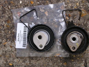
24. Before fitting the new tensioner, it is advisable to mark the end of the tensioner wire pointer with a drop of Tippex/white paint to alow it to be seen clearer during positioning | 24. Before fitting the new tensioner, it is advisable to mark the end of the tensioner wire pointer with a drop of Tippex/white paint to alow it to be seen clearer during positioning | ||
| − | [[File:Cambelt10.jpg|thumb|none|New Tensioner on | + | [[File:Cambelt10.jpg|thumb|none|New Tensioner on left with Pointer Marked]] |
25. Fit the new tensioner into position and secure with the centre bolt but leave it loose enough that the tensioner will wobble quite freely to give some freeplay while fitting the new belt. Ensure that the wire loop on the tensioner is hooked behind the bolt on the block. | 25. Fit the new tensioner into position and secure with the centre bolt but leave it loose enough that the tensioner will wobble quite freely to give some freeplay while fitting the new belt. Ensure that the wire loop on the tensioner is hooked behind the bolt on the block. | ||
| Line 218: | Line 201: | ||
http://wiki.seloc.org/a/Bleed_the_cooling_system | http://wiki.seloc.org/a/Bleed_the_cooling_system | ||
| + | |||
| + | CHOPPER. | ||
===NOTES=== | ===NOTES=== | ||
| Line 224: | Line 209: | ||
Another method to undo the crank bolt that has been used is jam the socket and breaker bar against the groung/something very rigid, and use the starter motor to turn the engine. The bolt being held will undo as the crank turns. Use this method at your own risk.... and make sure the car is out of gear when you do it | Another method to undo the crank bolt that has been used is jam the socket and breaker bar against the groung/something very rigid, and use the starter motor to turn the engine. The bolt being held will undo as the crank turns. Use this method at your own risk.... and make sure the car is out of gear when you do it | ||
| + | |||
| + | Another method to block the crank bolt when you remove/put the pulley : | ||
| + | [[File:manual.jpg|thumb|left]][[File:IMG_0065 (Personnalisé).JPG|thumb]] | ||
| + | |||
| + | |||
| + | * Make sure the car is out of gear | ||
| + | |||
| + | * Unscrew the starter (bolts n°25 & 27) and take off the rear closure plate (n°26). | ||
| + | |||
| + | * Then you have accesse to the flywheel... Now you need a strong cornered plate that you'll can wedge between the sump and the flywheel. Put it in the red position when you unscrew the pulley (like in the picture), put it in the blue position when you screw back the pulley... | ||
| + | |||
| + | * Just have to put back the starter and the closure plate when you're done. | ||
| + | |||
| + | |||
| + | |||
| + | |||
2. There have been a small number if instances reported where the cambelt centre tensioner bolt has become seized to the block through corrosion/overzealous tightening or the use of thread lock. Before stripping the engine to find this may be the case (and you now have a car that is incapable of being driven to a garage/mechanic), you may wish to check the tensioner bolt will loosen. This is possible by removing the upper cam belt cover before all else and trying to move the bolt a quarter turn. If it moves, tighten it back up and follow the normal procedure above | 2. There have been a small number if instances reported where the cambelt centre tensioner bolt has become seized to the block through corrosion/overzealous tightening or the use of thread lock. Before stripping the engine to find this may be the case (and you now have a car that is incapable of being driven to a garage/mechanic), you may wish to check the tensioner bolt will loosen. This is possible by removing the upper cam belt cover before all else and trying to move the bolt a quarter turn. If it moves, tighten it back up and follow the normal procedure above | ||
| Line 237: | Line 238: | ||
Thread here: http://forums.seloc.org/viewthread.php?tid=314945&page=1#pid5349364 | Thread here: http://forums.seloc.org/viewthread.php?tid=314945&page=1#pid5349364 | ||
| + | |||
| + | |||
| + | |||
| + | |||
| + | ===Tensioner=== | ||
| + | |||
| + | |||
| + | '''PLEASE ADD INFORMATION''' | ||
| + | |||
| + | Auto or Manual | ||
| + | |||
| + | I looked at the information on Eliseparts to ascertain if our engine was fitted with a manual or auto tensioner. | ||
| + | It sugested auto, i purchased an auto one but it turnd out to be a manual. | ||
| + | be warned, eliseparts will not allow you to return the miss purchased item and they stipulate this on line. | ||
===See Also=== | ===See Also=== | ||
Latest revision as of 15:28, 25 October 2025
PLEASE ADD INFORMATION, WORK IN PROGRESS
Part numbers
For auto tensioner:
Rover pt no, LHN100560
Gates pt no. 5497XS
Piper pt no TBP33
For manual tensioner (143 teeth):
Rover pt no. LHN100390
Gates pt no. 5416XS
Continental CT929 (belt only) / CT929K2 (with manual tensioner)
Piper pt no. TBP17 wide
Changing the Cambelt (Auto Tensioner inc Water Pump)
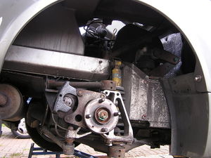
It is much easier to change the cambelt with the rear clam off but this is not necessary and access through the drivers rear wheel arch with the liner removed is still excellent compared to most 16v engines.
Instructions are for a "clam on" change
The rear of the car needs to be a high as possible to allow access to loosen and torque up the crank bolt (210Nm is tight)
((CLICK ON IMAGES TO ENLARGE ))
Tools Required
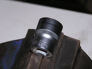
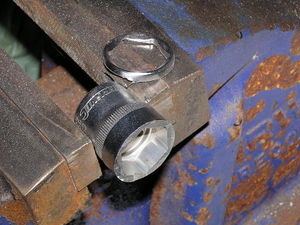
You will require a cut down 22mm socket to fit in the limited space between the crank pulley and the chassis (a 6 sided socket is stronger than a 12sided. Silverline do one for a couple of ££'s from Amazon)
You will also need a
. 1/2" breaker bar to loosen the crank bolt. As long as possible (don't try and use a ratchet handle, you'll break it and get a hernia to boot)
. a torque wrench capable of operating up to 210Nm (with a slim head if possible)
. A Rover K Series camshaft locking tool
Method
1. Run the rear of the car up on ramps if you have them and remove the rear undertray and diffuser. Loosen the RHS rear wheel nuts while the weight of the car is still on the wheel
2. Remove the spark plugs (this will allow the engine to be turned over much easier using the crank bolt as required below
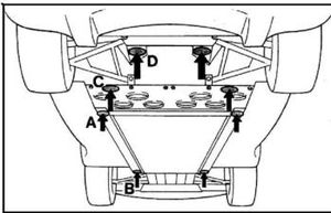
3. Jack up the RHS of car higher still and place axle stands at the B and C positions in the diagram (if you don't have ramps then jack and support with axle stands in stages, as the tilt on the car can easily cause it to slip off a jack on it own)
.
Try and get the car high enough that you can kneel with your head inside the rear wheel arch (when the liner is out) as this is a comfortable working position allowing you to reach into the engine bay through the arch
4. Move the ramp out of your way and remove RHS rear wheel
5. Remove RHS rear wheel arch liner
6. You may wish to remove the brake disc on the RHS rear wheel to allow greater access into the wheel arch when working (it is not necessary to do this)
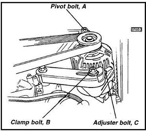
7. Loosen the pivot bolt and clamp bolt on the alternator
8. Loosen the adjuster bolt to move the alternator towards the engine and provide slack on the the belt. The bolt has a fine pitch so expect to turn it many times before the belt slackens (If you intend to refit the existing alternator belt, before undoing the adjuster bolt, mark the position of the clamp bolt on the slotted bracket, so that you know exactly where to tighten the belt up to on reassembly)
9. Remove the alternator belt
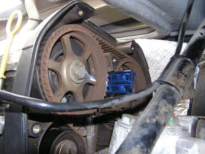
10. Unbolt the upper cam belt cover and manoeuvre it upwards and out via the the engine bay (the cover to clam clearance is tight, but it will come out with minimum force if jiggled about a bit)
Ensure that you do not lose the rubber seal that press fits onto the bottom edge of the upper cover
11. Before loosening the crank bolt place a suitably sized screwdriver or allen key in the visible flywheel ring gear next to the drivers side driveshaft to prevent the engine rotating (I found an allen key much less likely to slip)
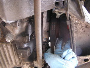
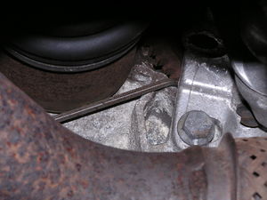
12. From under the car and using the breaker bar with the cut down socket, loosen the crank bolt (you are likely to have to brace your knees/feet against the underside to gain enough purchase to undo the bolt. Folk on here have snapped breaker bars doing this, so take care)
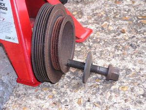
13. Remove the crank bolt, the large washer (note orientation) and then the crank pulley
14(a). Remove the lower cam cover
14(b). Replace the crank bolt (only) and hand tighten.
15(a). Before removing the cambelt the engine requires to be placed in a known positioned with No1 piston (closest to belt end) at 90deg BTDC. As a visual aid to help find 90 BTDC, place a long screwdriver/large tie wrap/clean garden cane etc etc down through hole where you removed the spark plug on cylinder 1. It will rest on the piston crown and rise and fall with the engine rotation as required in part 16 and indicate piston location and direction. ***Make sure that whatever you use is long enough so that it does not fall into the engine at piston BDC !!! ***
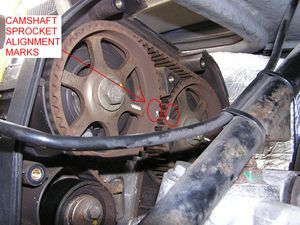
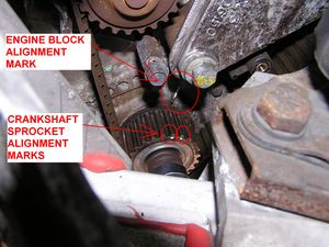
15(b). Its worth highlighting the camshaft sprocket alignment marks, the crankshaft sprocket alignment marks and the engine block alignment mark with some Tippex (or white paint) for ease of viewing
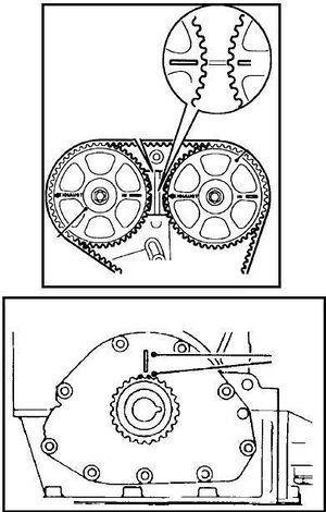
16. Remove the screwdriver/allen key from the flywheel teeth, and with the car out of gear. Turn the engine using a rachet/spanner on the crank bolt (only ever turn clockwise), until the camshaft and crank shaft alignment mark line up as above AND the visual aid in cylinder 1 shows the piston is half way up the cylinder on the rise. Camshaft sprocket marks should face each other in a line with the centre bolts of each shaft. The crank dimple marks should straddle the block mark.
17. Replace the screwdriver or allen key in the flywheel and place the camshaft locking tool into place
18. Mark the old belt/sprockets at both cams and on the crank. When the old belt is off, transfer these marks to the new belt (carefully count the belt teeth). When fitting the new, the marks will ensure it is not out by a tooth anywhere along its length (the K series will run without damage when the belt is out by a tooth either way but not very well!!).
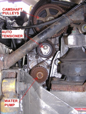
19. Unbolt the tensioner centre bolt, remove the tensioner and slide off the cambelt.
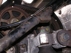
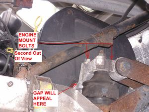
20. The engine mount prevents the old belt from being removed completely. There are two ways of getting the old belt out and new one in
20a (Thanks to Dave Andrews for this tip): The easiest method is to remove one bolt on the engine mount at a time and weave the belt in between the bolts. Slacken both so that the engine drops by 12-15mm or so. Remove one bolt and push the belt into the gap between. Replace the bolt and tighten to where it was (I.E. 12mm gap), then remove the other bolt and push the belt the rest of the way through the gap. Reverse the process to get the new belt in, then do up both bolts to the correct torque.
20b The alternative method, is to place a trolley jack under the engine (use a piece of wood between to spread the contact load), jack the engine up slightly and remove the engine mount bolts completely. Takes a bit longer and if the engine moves ever so slightly back or forward it can be a PITA to get the bolts started in the threads again
Waterpump Change
21 If you intend to change the waterpump as well (and if you're in here already its probably worth it !!), now is the time to do it. Drain the coolant by undoing and hoses that enter both side rails at the rear of the car
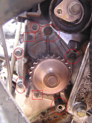
22. Unbolt the old pump and remove it. (Expect more coolant to flow from the engine block). There are 6 bolts circled in the photo. The top left is bolted from the rear side, the bottom right is a pillar bolt (used for the front cover as well) and there are two dowels, squared in the photo. Check that the old rubber sealant ring was removed with the old pump and if there is any corrosion around the face/dowels remove with wet an dry paper. The block surface should be clean to allow the new pump to fit well
23. Ensuring the new sealant ring is in place in the groove on the new pump and fit the pump (you can use some (proper) automotive RTV silicon to hold the new sealant ring in place if required). Tighten the bolts in stages alternating between diagonally opposite bolts to 10Nm
Cambelt Continued
24. Before fitting the new tensioner, it is advisable to mark the end of the tensioner wire pointer with a drop of Tippex/white paint to alow it to be seen clearer during positioning
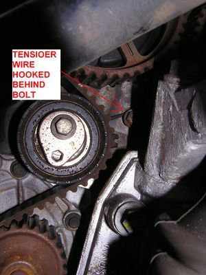
25. Fit the new tensioner into position and secure with the centre bolt but leave it loose enough that the tensioner will wobble quite freely to give some freeplay while fitting the new belt. Ensure that the wire loop on the tensioner is hooked behind the bolt on the block.
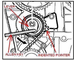
The tensioner lever (the part where the allen key fits, should be at the 9 o'clock position)
26. Fit the new belt onto the crank pulley first. If you marked the belt as per section 18 above, line up the mark on the belt with the sprocket mark. Fit the belt so that approx half of the width is on the sprocket/half is hanging off the front edge. Again this gives you more leeway/flex with the belt as you feed it on.
27. Keeping the long RHS of the belt taught, feed it over the RHS (exhaust) cam sprocket then over the LHS (inlet) cam sprocket, again lining up the white marks you placed on it earlier and again only pushing the belt on half way
28. Feed the belt up around the water pump then around tensioner. Once around all the mounting points you can then push the belt fully onto all the sprockets until seated fully
29. Tighten the tensioner centre bolt, not fully, but enough to pull it against the block
30 From the service manual:-
30a. "Tighten the centre bolt until it is just posible to move the tensioner lever"
30b. "check the belt is central around gears and pulleys
30c. "Using a 6mm Allen Key, rotate tensioner anti-clockwise and align the centre of the indent on the tensioner pointer to the index wire
ENSURE that the pointer approaches the index wire from above. Should pointer go past index wire, release tension completely and repeat tensioning procedure"
30d. "Ensuring that the pointer maintains the correct position, tighten centre bolt to 25Nm"
(It is quite difficult to hold the allen key on the lever and use a torque wrench in this location. If you tighten this bolt up using the "calibrated hand" method, do not overtighten the bolt.
31. Remove the cam locking tool and the crank locking allen key/scredriver and using a ratchet on the crank bolt, rotate the engine 2 turns clockwise. Check the tensioner pointer is still in the correct position
32. Remove the crank bolt, refit the cambelt lower cover.
33. Ensuring the mating surfaces of the crank pulley, washer, bolt and sprocket are clean, refit the crank pulley, washer and bolt. (Do not use a thread lock compound). Make sure the notch on the pulley is keyed to the crank before tightening the bolt hand tight
34. Replace the crank locking allen key/screwdriver and torque the crank pulley to 210Nm. This is a significant force even with a long torque wrench. Do not be tempted to just beef up the bolt with a big spanner, numerous instances of the the crank nose being worn away, the pulley undoing and the crank sprocket sliding off because of a loose bolt have been documented with the K series
35. Remember to remove the crank locking allen key/screwdriver !!!!
36. Refit the alternator belt
37. Refit the upper cam belt cover (be careful that the rubber sealing gasket on the lower edge is in the correct place. Its easily knocked off)
38. If you have changed the water pump, reconnect all coolant hoses and refill the system with new coolant.
39. I always turn the car over on the starter with the spark plugs removed just as a double triple check that all is well. (not advisable on cars with coil packs as they can be damaged. Better to remove the power to the fuel pump) If it doesn't rattle like a bag of nails :-), then refit the spark plugs and leads, start the engine
40. Lower the car and bleed the cooling system per the service manual or
http://wiki.seloc.org/a/Bleed_the_cooling_system
CHOPPER.
NOTES
1. Alternative methods used to lock the crank include having the car in gear and an assistant press on the brakes VERY hard. It has worked for some and it appears OK for loosening the crank bolt but when doing up any slipage will throw out the timing !!!
Another method to undo the crank bolt that has been used is jam the socket and breaker bar against the groung/something very rigid, and use the starter motor to turn the engine. The bolt being held will undo as the crank turns. Use this method at your own risk.... and make sure the car is out of gear when you do it
Another method to block the crank bolt when you remove/put the pulley :
- Make sure the car is out of gear
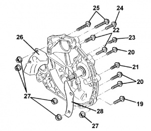
- Unscrew the starter (bolts n°25 & 27) and take off the rear closure plate (n°26).
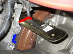
- Then you have accesse to the flywheel... Now you need a strong cornered plate that you'll can wedge between the sump and the flywheel. Put it in the red position when you unscrew the pulley (like in the picture), put it in the blue position when you screw back the pulley...
- Just have to put back the starter and the closure plate when you're done.
2. There have been a small number if instances reported where the cambelt centre tensioner bolt has become seized to the block through corrosion/overzealous tightening or the use of thread lock. Before stripping the engine to find this may be the case (and you now have a car that is incapable of being driven to a garage/mechanic), you may wish to check the tensioner bolt will loosen. This is possible by removing the upper cam belt cover before all else and trying to move the bolt a quarter turn. If it moves, tighten it back up and follow the normal procedure above
Useful video:
http://www.mgf.ultimatemg.com/group2/engines/index.htm
Useful link to another guide fitting the manual tensioner http://www.tadts.com/instructions/engine/100016.html
Quick Guide
Thread here: http://forums.seloc.org/viewthread.php?tid=314945&page=1#pid5349364
Tensioner
PLEASE ADD INFORMATION
Auto or Manual
I looked at the information on Eliseparts to ascertain if our engine was fitted with a manual or auto tensioner. It sugested auto, i purchased an auto one but it turnd out to be a manual. be warned, eliseparts will not allow you to return the miss purchased item and they stipulate this on line.
See Also
PLEASE ADD INFORMATION
