Difference between revisions of "How to Rebuild a Brembo Caliper"
| Line 58: | Line 58: | ||
| + | [[Image:Brembo_Caliper_13.JPG]] | ||
Revision as of 23:39, 26 February 2007
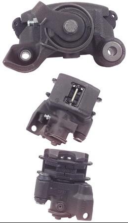
Lotus Elise Rear Caliper Rebuild and Upgrade
The service manual claims the Brembo Calipers fitted to the rear brakes of the Elise are not serviceable.
These instructions were developed by disassembling and reassembling many calipers and are not perfect.
The Lotus Elise rear caliper is criticized as being too small. The rear caliper piston size can be increased from the standard 36mm to 38mm diameter.
The stock calipers can be machined to accept a 38mm piston and sleeves.
For the larger piston, you will need a Brembo 38mm seal, part number 05.5955.57
This conversion still allows the use of all the other standard size parts that come in the KC-83017 kit. A Brembo 40mm seal is available as part number 05.5955.58
Procedure
Disassembly
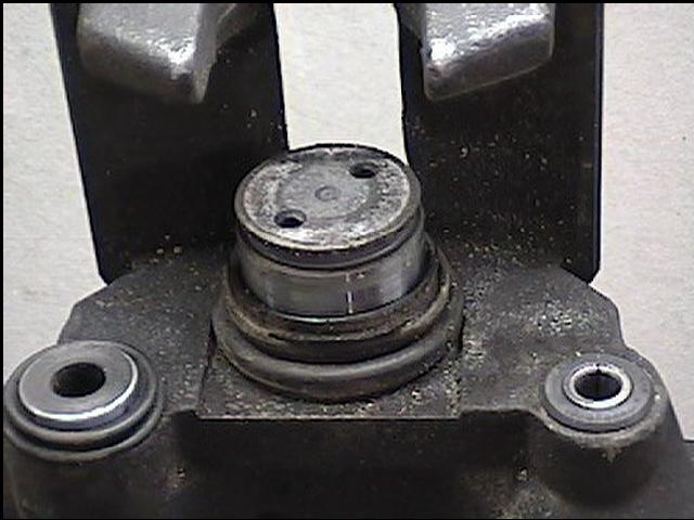
Unscrew piston as far as it will go using either a windback tool or stout needle nose pliers, one tip in each hole. Rotate counterclockwise.
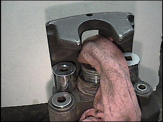
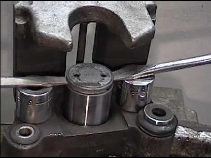
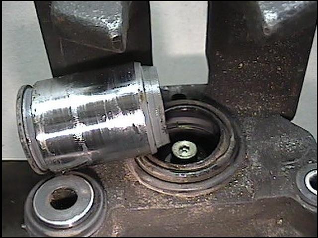
As the dust boot stretches, pull it out of the groove. The piston can be pried out with two screwdrivers. An internal snap ring holds it tightly, so be prepared to try a few times and apply some effort. Before it pops, it will feel “springy.” When the snap ring does pop, the piston will go flying, so put a rag over it to keep it from falling. You can use a socket on each side to support the screwdriver.
Here’s the prying position (without the dust boot and rag.) From this image you can get a perspective of how far up the piston will rise without coming out. The piston can also be
removed with air pressure into the brake line supply inlet.
Once the piston is out, do not turn the caliper over. There are several loose pieces inside that may fall out.
Remove the dust boot.
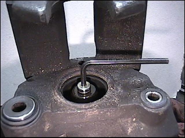
With a 4.5 mm allen wrench, remove the screw. This screw has an O-ring around the head, so do not reach in and use pliers. It is also held in with thread lock glue, so it feels a little stuck before it comes loose. It may also drag the whole way out. Use the proper allen wrench, since the metal is soft and you’ll easily round the hole.
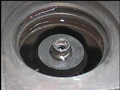
After the screw is removed, the threaded disc can be unscrewed and removed. This disc pushes on the inside of the piston when pulling on the parking brake.
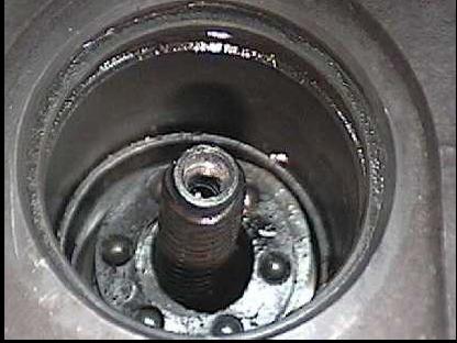
Without the disc, a ball bearing race, a snap ring, and two washers will be visible in the bore. Turn the caliper over to remove them.
Here’s what will fall out:- Ball bearing Flat washer Wave washer Snap ring
Removing the worm thread shaft is next. Look down into the bore for the internal snap ring. It has several tabs bent to point up at you. With a flat screwdriver, pry the tabs at the ends of the snap ring towards the center of the bore and disengage it from the groove in the wall. Now the worm shaft (and snap ring) can be removed. Notice the tabs. Unscrew the hex stop peg in the boss of the caliper. Remove the parking brake lever, parking brake shaft dust seal, and push the shaft into the caliper body. Remove the ball bearing drive plate, the needle bearing, and the flat washer. The flat washer tends to stick in the caliper, be sure not to miss it. Remove the old piston seal.
Reassembly
Install a new parking brake drive plate shaft O-ring, if needed. Reinstall the flat washer, needle bearing, and ball bearing drive plate of the parking brake in the caliper body. Make note of where the three ball bearings are; you will need to mate them with the driven plate later.
The internal assembly will go back together in this order: Wave washer Flat washer Ball bearing Cone screw.
Use some thread lock on the O-ringed screw on reassembly. Install a new O-ring on the screw. To reassemble the caliper, insert assembly into the piston and snap the (coat-hanger quality) internal snap ring into the piston. The snap ring groove is just inside the piston. Take the internal snap ring with the tabs, point the tabs downward, and use the tabs to clip the snap ring into the bottom edge of the piston. Then screw the worm shaft into the piston as far as it will go. Install the new piston seal. Stretch the new dust boot over the bottom of the assembled piston, leaving the lower edge of the boot to hang down. You will have to hold the piston over the bore and insert the boot lip into the groove all the way around before inserting the piston into the bore. The boot should look even (no bumps) if done properly. Make note of where the ball bearing detents are. This is the tricky part. With the boot in the groove, center the piston to begin pushing it into the bore. Use a c-clamp with a socket covering the parking brake shaft sticking out the bottom, making sure the clamp is pushing the piston straight down. Besides the normal problem of getting past the boot lip and the seal, the driven plate detents and the drive plate ball bearings must mate, otherwise you will not be able to push the piston down far enough for the internal snap ring to find it’s groove. If the clamp seems to come to a stop and you have not heard the snap ring snap into place, try to rotate the clamp to rotate the piston and line up the ball bearing detents. A second way is to temporarily attach the parking brake lever under the clamp to rotate the lever, which will move the drive ball bearings back and forth to line everything up. Rotate the lever clockwise when facing the lever, as this also screws the threaded shaft into the cone shaped washer (ensuring that the piston is not bottoming on the parking brake adjustment.) In any case, the piston will seem to be very low, lower than the dust boot wrinkles, before the snap ring engages. If the snap ring does not engage, the parking brake system has nothing to push on to “disengage.”
Hint: Sometimes you can't push on the brake lever arm with the C-clamp to insert piston, you need to take off the arm and push on casting using socket.
When the snap ring engages, reinstall the hex head stop peg. Using the parking brake lever, rotate the parking brake shaft while looking down into the stop peg boss. You will see the detent in the foot of the worm shaft. Screw in the stop peg so it engages the detent. You can check the proper operation by now rotating the parking brake lever again (which will push the piston out) and then rotating the opposite direction (which should slightly pull the piston back in.) With larger swings of the lever, this becomes a ratcheting action, so repeated back and forth with the lever will eventually move the piston further and further out; if the snap ring is engaged properly, the piston will slightly retract after each lever movement. Once installed, the new 38-mm calipers look exactly like the stock system.
Better brakes without changing appearance or same appearance without admitting the brakes are modified.
Notes: The brakes usually have to bled twice. It seems that air is trapped in the piston (the recess for the threaded parking brake adjustment rod) that isn’t flushed out during caliper installation. The O-ring screw is a 10-32 thread. About 10% of the time it breaks when trying to remove it.
