Difference between revisions of "Geo Alignment Rig (Home Made)"
hbaumhardt (talk | contribs) |
hbaumhardt (talk | contribs) |
||
| Line 77: | Line 77: | ||
4. Loosen front TRE locknuts and rear toe-link locknuts | 4. Loosen front TRE locknuts and rear toe-link locknuts | ||
| − | 5. Take toe measurements, adjust and measure again repeatedly (see the service manual for HOW TO) | + | 5. Take toe measurements from the rear (thats whats moving), adjust and measure again repeatedly (see the service manual for HOW TO) |
Revision as of 20:48, 3 July 2007
Intro
Being a budget class A racer and having forked out lots of £45s to the local Hunter place, following some questionable results recently I want to be able to mess around with the geo (camber and toe) myself so built a rig for £5.98 (normal price £19.98).
Note that you kind of need to understand suspension settings and what you are doing on an Elise, this is not a “zero to geo hero” guide. See see:Geo Setups for standard settings.
Preparation
The car needs to be on level(ish) ground, centre the steering wheel, load up the cabin to usual racing/driving around weight and hot tyre pressures.
Measuring Toe
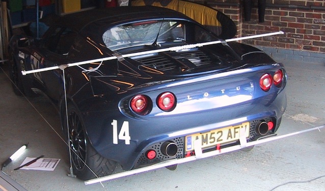
1. Homebase for two bits of 2400mm rigid aluminum (16mm ally channel as they don’t to tubes, but I’ll call them “poles” for now) and 10m of nylon cord or fishing line.
2. The rear track of the S2 Elise is 1700mm and to allow for bodywork and working space cut the poles to 2000mm, mark the centre and drill a 4mm hole 900mm each side from the centre on each pole.
3. Find the centre of the car measure from the wheel track and mark up (front towing post is near-ish.) with tape for coarse alignment.
4. Tape the poles to the front and back of the car aligning centre marks (spirit level to avoid droopidge).
5. Run string through the holes; big knot in one end and tie off the other, make sure it passes near the wheel centers.
6. Measure from the centre of each wheel and adjust the string until its parallel side to side for fine alignment.
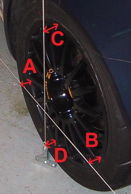
7. Use a ruler to measure mm distance from front and rear of rim to string and subtract front from rear for the TOE_IN_MM (minus is OUT plus is IN).
8. If your want toe in degrees then convert using Excel =DEGREES( ASIN( TOE_IN_MM / ( RIM_DIA_INCHES * 25.4 )))
Measuring Camber
1. To measure camber I made a plumb line out of stuff lying around (net curtain rail, string, iron weight) and taped the rail across the car to give me something to hang the plumb from.
2. Measure distance from top & bottom of the rim to the plumb line string and subtract top from bottom for CAMBER_IN_MM. (minus is GOOD)
3.Calculate camber in degrees using Excel =DEGREES( ATAN( CAMBER_IN_MM / ( RIM_DIA_INCHES * 25.4 )))
Measuring Castor
CBA
Accuracy
A minus B is TOE_IN_MM (Minus is toe OUT plus is toe IN)
D minus C is CAMBER_IN_MM (You want an negative number)
Either use RIM_DIA_INCHES*25.4 or take the actual MM measurement of the diameter you are measuring from A to B and C to D
Reading the markings on the ruler seems to be the limit on accuracy - around plus/minus 0.5mm on each measure which is 0.07° in toe or camber so worst case compound error gives plus/minus 0.14° on each setting.
Adjusting Camber
Once you have the plumbline measure you don’t need the string any more (and the wheel needs to come off) as each 1mm camber shim is 0.25 degree front and 0.30 degree on the back - just add or remove the number of shims from the measurement to get what you want (see the service manual for HOW TO).
Whilst your there, don’t forget to check or change the rear plinth bolts to A117W7212F 10.9 grade
Adjusting Castor
CBA - see the service manual for HOW TO
Adjusting Toe
1. Jack the car onto 4 even blocks of wood for working room (front of an S2 with low ride height)
2. Rear diffuser/under-tray off
3. Secure the steering wheel with a strap
4. Loosen front TRE locknuts and rear toe-link locknuts
5. Take toe measurements from the rear (thats whats moving), adjust and measure again repeatedly (see the service manual for HOW TO)

