Difference between revisions of "Remote Boot Release for S2"
| Line 140: | Line 140: | ||
##There are 4 of those rawlplug-screw efforts holding it in place. They may need some persuading to come out (use a flat headed screwdriver). | ##There are 4 of those rawlplug-screw efforts holding it in place. They may need some persuading to come out (use a flat headed screwdriver). | ||
##There is also some Silkaflex/Bathroom sealant black gunky stuff holding it in place. It will come off with a but of persistance. | ##There is also some Silkaflex/Bathroom sealant black gunky stuff holding it in place. It will come off with a but of persistance. | ||
| − | #You will now be able to see the bottom of the lock barrel. Put your key in the lock and turn it while looking at the underside of the boot lid. Notice how when you turn it, it turns the cam bit slightly and it pulls a small spring/bit of wire which pulls on the lock mechanism to release it. This is what we are going to replicate with the | + | #You will now be able to see the bottom of the lock barrel. Put your key in the lock and turn it while looking at the underside of the boot lid. Notice how when you turn it, it turns the cam bit slightly and it pulls a small spring/bit of wire which pulls on the lock mechanism to release it. This is what we are going to replicate with the bicycle cable. |
| − | ## | + | #Feed the outer cable (from left to right) through the boot-lid support bracket (see image). |
| + | #If your bicycle cable has a connector on both ends of the cable, cut the smallest of the two connectors off with a pair of sharp wire cutters and feed it through the outer cable. | ||
| + | #Pick up the black cover you just removed and hold it as though there it is fitted to the car. Notice on the right is a small hole in addition to the screw holes. | ||
| + | ##Take on of your bike cable adjusters and remove the nut from it. | ||
| + | ##Put the "bolt" bit of the adjuster through the hole and attach the nut to the other side - tighten it up so it stays there. | ||
| + | ##Feed the bike cable through the middle of the adjuster, the adjuster will stop the outer cable going through it. | ||
| + | ## | ||
==Random Questions== | ==Random Questions== | ||
Latest revision as of 21:17, 17 April 2011
There is a kit available from Elise Parts for an S1 remote boot release. However the lock mechanism is mounted on the engine cover on an S2, not on the car, so to use this kit on an S2 it would require mounting the solenoid etc. on the engine cover its self. This isn't something I wanted to do, so I used a bit of ingenuity and put something together myself.
I (nor SELOC or anyone else) take any responsibility if you break your car as a result of following this guide. This is a guide, not a fool proof set of instructions, as such it should be used with this in mind. Be warned: it does involve some dicking about with the cars wiring, nothing major, but you have to get a 12v feed and an earth from somewhere. Remember to disconnect the battery before you start cutting wires!
I did this mod on my '04 non-touring pack 111R.
Shopping List
- 2m of bicycle brake cable (both inner & outer parts)

- 2x bicycle brake cable adjuster

- Central Door Locking Solenoid - I used a YD79L from Maplins - it includes several things I used in this HowTo. Don't be tempted to buy a cheap kit from eBay that looks the same, I got one and it broke within 2 presses of the button

- A button

- A 4-pin 12v automotive relay - you need one which has an open switch when the coil is not energised, and closed when it is energised.

- Some male & female spade connectors
- Some cable ties
- Electrical insulation tape
- Double sided tape / velcro
- Some wire (I used about 6m or so of 7 amp wire, available from Halfrauds for about £3.79 per 6m reel). The amount you will use/need will depend on where you choose to get the power/ground from, where you want to locate your button, the solenoid and the relay.
- Beers.
Tools
- Screwdrivers
- Cable cutters
- Stanley knife / cable stripper
- Pliers
- Drill & drill bits
- Allen keys
- Socket set
- Spanners
- T50 torx/star drive socket
- Sandpaper
Wiring
The wiring required is pretty simple, but it is pretty important you understand it because if you connect the wrong thing to the other wrong thing there is a good chance you can do some damage to either your car or yourself. Before you start cutting wires, disconnect your battery.
If you don't understand what a relay is or does, read the Random Questions bit of this page. It will hopefully make a lot more sense then.
Ground and Live sources
There are a number of places you could get a ground and live connection in the car, but I am going to assume you are going to use the same place as me: the auxiliary power socket between the seats.
Two wires run into the auxiliary power socket connector, a ground wire (black) and a 12v live wire (purple). You will need to splice another wire into both of these wires.
"Why use the auxiliary power socket?" I hear you ask. Because it already uses a reasonable high ampage fuse (20 amps) so can take the current from using the solenoid easily. And the auxiliary socket circuit (in the car) isn't shared with anything else - so if you do cock it up, there isn't anything else you can fry on the same circuit. The interior light for example is shared with the alarm system (and you don't want to be messing with that!).
The relay
The relay will have pins on it corresponding to the two circuits which run within it (the coil circuit and the switch circuit).
I will assume your relay has the same numbers on is as mine does (If your relay does not have the same numbers on the pins, normally a small circuit diagram on the side of the relay will describe what each pin refers to).
- Pin 85 - Coil live
- Pin 86 - Coil ground
- Pin 30 - Switch live
- Pin 87 - Switch ground
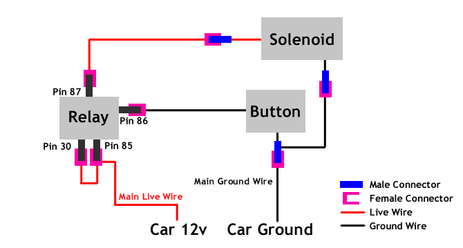
The circuits
Two simple circuits need to be made - one with a button in it, the other with the solenoid in it. Parts of both of these circuits run through the relay.
If you can read a circuit diagram, you can probably make sense of this diagram. If you can't allow me to explain.
- Circuit 1 - "Button circuit"
- This circuit runs from the 12v power supply (ie a live in the car somewhere), then through the button, then through the relay's coil, and finally to a ground in the car.
- Circuit 2 - "Solenoid circuit"
- This circuit runs from the 12v power supply through the switching part of the relay, then through the solenoid, and finally to a ground in the car.
What Circuit 1 does is when the button is pressed, it completes the circuit, and energises the coil in the relay. The energised coil closes the switch on the Circuit 2 part of the relay. Circuit 2 is now complete, so the solenoid is activated. Circuit 2 will remain complete until the button in Circuit 1 is released.

The numbers in the diagram above in the relay (the box at the top) correspond to the pins on the relay.
The wiring
I decided to buy red and black cable and use the red for the 12v feed, and black for ground. I got 6m of both (and used a lot more of the red than black). How much cable you will use will entirely depend on where you decide to mount the solenoid in the engine bay, the relay and the button. Just unravel some cable and lay it out through the route you are going to send the wire before cutting some off. More about which wire goes where later.
How to do it
NOTE: My car doesn't have insulation behind the bulk head covering as it isn't a "touring" model. Yours may well have insulation which you have the choice of removing first, or finding an alternative route for the wiring. An alternative might be the slight recess which the boot hinges attach to.
- Remove both seats.
- The passenger seat has 4 allen bolts. The drivers seat has 2 hex bolts & two allen bots.
- Note: there is a small seat runner stop on the drivers seat. Don't loose it!
- Undo the seat and top mounts of both the seatbelts.
- Undo the seatbelts from the side of the seats (requires a 17mm spanner).
- Unclip the plastic covers over the top seatbelt mounts.
- Unbolt top mount of the seatbelt from the rollover hoop (requires a T50 torx/star drive socket and a BIG socket wrench, as it is bloody tight!).
- Remove the centre console storage pocket.
- Undo the screw at the bottom of the pocket from the top.
- Then undo the two screws you can see holding the lower part in.
- Carefully lift it out the way, and disconnect the plug on the back of the auxiliary power socket.
- Remove the speakers.
- Unclip the cover over the speaker (if you have any), you may need a flat-head screwdriver to prize it off.
- Undo the securing screws holding the speaker in and carefully remove the speaker from the housing making sure you don't snag the speaker wires.
- Disconnect the wires to the speakers.
- Remove the bulk head covering.
- Undo the 5 (?) screws / plugs securing the cover to the bulkhead. These may need persuading with a flat-head screwdriver to come out.
- The whole cover needs to be "manipulated", shall I say, to get it in/out of the car!
- Start at the bottom on one side near the seatbelt reels. You need to carefully bend the cover out from behind the roll-over bar cover.
- Once the bottom is out, work the top out in a similar way. It does need a bit of restrained brute force, but it will come out.
- Disconnect the connector on light in the middle of the panel before trying to remove it from the car entirely.
- Drill a hole in the bulk head covering for your button.
- Decide where you want your button to be. I chose to put my button on the bit which covers the seatbelt reel - there was plenty of space here and it was easily accessible.
- Double check there is enough clearance in this button location.
- Measure your button and pick an appropriate sized drill bit to drill a hole.
- Create a bit of a dint for the drill bit with a pointy object, this will stop the drill bit skipping about (you may wish to drill a pilot hole first).
- It is only plastic so remember it wont take much to drill through. Also, don't get over-zealous with the drill, if you bugger this bit up you will notice it!
- Test fit your button and fettle the edges of the hole if you need to.
- Drill a hole through the bulkhead for the wires to enter the engine bay.
- Check for any pre-existing holes in the bulkhead - I had one on the drivers about 6-8" to the right of where the speakers sit. I just made this slightly bigger.
- Check BOTH SIDES of where you are drilling.
- Choose a sensible sized drill bit large enough to fit 2 cables through.
- Use minimal pressure on the drill - it is only fibreglass it isn't especially resilient to a drill!
- Test fit a couple of cables to make sure they fit through easily enough - it doesn't need to be "tight", but at the same time it doesn't want to be as slack as Kerry Katona!
- Important - If you haven't already done so, disconnect the battery (you might just be able to remove the fuse).
- Splice a 12v and a ground "main" wire into the 12v and ground cables going to the auxiliary power socket.
 Wiring diagram
- Cut through both of the 12v and ground wires - leave enough spare cable on the connector end to allow you to attach a male blade connector (you might need to cut back the plastic tape stuff holding the two wires together - be careful when doing this).
- Strip and attach a couple of male blade connectors onto the bits of wire you left on the connector which connects to the auxiliary power socket.
- Decide approximately where you want your relay to live (against the bulkhead is a good idea), and unwind enough wire to run from this place to the aux power socket wires (plus a bit extra). Do this twice (one 12v, one ground).
- Strip and wind the ends of your new "main" 12v wire together with the car's 12v wire, attach a female connector onto this wire and connect it to the aux power socket. Do the same with the new "main" ground wire.
- Put a female blade connector on the end of your "main" ground wire.
- Cut a short 3" piece of wire to join the 30 and 85 pins on the relay to the "main" 12v wire.
- Put a female blade connector on the end of a short (3-4") piece of wire - connect this to pin 30 on the relay.
- On the other end of the short wire, wind the other ends of this wire into the 12v "main" wire - attach both wires to the same female blade connector - connect this to pin 85 on the relay.
- Run 2 lengths of wire for your button.
- At one end of one of the lengths of wire, attach a female blade connector and connect it to pin 86 on your relay. Attach the other end to your button.
- From the other terminal of your button, run the second wire back to the your "main" ground wire - do not put a connector on this yet.
- Run a live and ground wire from the relay, through the bulkhead, to where you would like the solenoid to live in the engine bay.
- On the relay side of the live wire, attach a female blade connector and attach it to pin 87 of the relay.
- On the engine bay side of the live and ground wires, attach a female blade connector to each wire.
- Check your solenoids connectors - if you need to, replace the connectors with a male blade connectors - this way you can switch the cables round if you connect them up and the solenoid moves the wrong way (which it probably will).
- Take the ground wire running from the solenoid through the bulkhead to the button ground wire and twist the ends together - attach a both wires to the same male blade connector and connect it to the "main" ground wire.
- In theory (and if I've not forgotten anything) you should have a everything completely wired up.
- Check the diagram on the right to make sure it matches up.
- Check all the connections are solid, and if you aren't using insulated connectors, wrap some insulation tape around the connections to not leave any exposed wire.
- Be brave, attach the battery terminals again and press the button. You should hear the relay click and the solenoid move.
- If it doesn't check all your connections are solid and that the fuse for the auxiliary power socket is not broken.
- Check the solenoid is PULLING in when you press the button - if it isn't, switch the two wires near the solenoid around.
- Get a beer / drink or something. If it was as hot and sunny outside as it was when I was doing this, check the back of your next/face/arms etc for sunburn and apply anti-sunburn cream where needed.
- Open the boot lid and prop it open.
- Remove the black cover which is on the underside of the boot-lid (it covers the lock barrel & the mechanism.
- There are 4 of those rawlplug-screw efforts holding it in place. They may need some persuading to come out (use a flat headed screwdriver).
- There is also some Silkaflex/Bathroom sealant black gunky stuff holding it in place. It will come off with a but of persistance.
- You will now be able to see the bottom of the lock barrel. Put your key in the lock and turn it while looking at the underside of the boot lid. Notice how when you turn it, it turns the cam bit slightly and it pulls a small spring/bit of wire which pulls on the lock mechanism to release it. This is what we are going to replicate with the bicycle cable.
- Feed the outer cable (from left to right) through the boot-lid support bracket (see image).
- If your bicycle cable has a connector on both ends of the cable, cut the smallest of the two connectors off with a pair of sharp wire cutters and feed it through the outer cable.
- Pick up the black cover you just removed and hold it as though there it is fitted to the car. Notice on the right is a small hole in addition to the screw holes.
- Take on of your bike cable adjusters and remove the nut from it.
- Put the "bolt" bit of the adjuster through the hole and attach the nut to the other side - tighten it up so it stays there.
- Feed the bike cable through the middle of the adjuster, the adjuster will stop the outer cable going through it.

Random Questions
- What is a relay?
- A relay is a method way of using a low current/voltage switch to safely connect/disconnect a higher current/voltage circuit, useful when switching motors etc on and off.
- How does a relay work?
- Very simply - a low voltage circuit is used to provide power to a electromagnetic coil which, when active, will connect another higher voltage circuit.
- Why a relay?
- You need a relay because you will burn the switch out with the current required to power the solenoid. If you put a switch into the low voltage coil circuit, by turning the switch on, you can control if the coil is on or not (thus connecting or disconnecting the high voltage circuit).