Difference between revisions of "Reversing sensor"
| Line 9: | Line 9: | ||
Think Logically and it is all straight forward. | Think Logically and it is all straight forward. | ||
| − | The kit comes with many parts but I started first with the aluminium self adhesive foil strip. It has a connector at one end that you will later attach to the ECU. Start with this in the lowest point of the boot in closest proximity to the battery | + | The kit comes with many parts but I started first with the aluminium self adhesive foil strip. It has a connector at one end that you will later attach to the ECU. Start with this in the lowest point of the boot in closest proximity to the battery. |
| − | [[File: | + | [[File:Antennaconnection.jpg|200px|thumb|left|sensor connector]] |
Then fix the strip right around the boot as low as possible. By the way always a good idea to make sure the inside of the shell is clean and dust free. | Then fix the strip right around the boot as low as possible. By the way always a good idea to make sure the inside of the shell is clean and dust free. | ||
| − | [[File: | + | [[File:Reversingantenna.jpg|200px|thumb|left|sensor fixed right around the boot]] |
| + | |||
| + | Next up attach the ECU to the reversing lamp to provide the power as and when reverse is engaged | ||
| + | |||
| + | [[File:Rearlightcluster.jpg|200px|thumb|left|red and black ECU cables crimped to the +v and -ve of the reversing lamp]] | ||
| + | |||
| + | |||
[[File:RearlightclusterPD1attached.jpeg|200px|thumb|left|Rear light cluster with PD1 attached to +ve and -ve reverse lamp feed]] | [[File:RearlightclusterPD1attached.jpeg|200px|thumb|left|Rear light cluster with PD1 attached to +ve and -ve reverse lamp feed]] | ||
Revision as of 08:04, 2 June 2014
PD1 Reversing Sensor installation
This is my second installation of the Parking Dynamics PD1 sensor and some of the photographs originate from MY2006 Exige installation and some from a MY2010, but I am guessing nothing serious has changed in the intervening time.
The instructions are very good but if anything make it sound more complex than it is.
Think Logically and it is all straight forward.
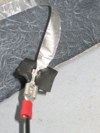
The kit comes with many parts but I started first with the aluminium self adhesive foil strip. It has a connector at one end that you will later attach to the ECU. Start with this in the lowest point of the boot in closest proximity to the battery.
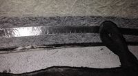
Then fix the strip right around the boot as low as possible. By the way always a good idea to make sure the inside of the shell is clean and dust free.
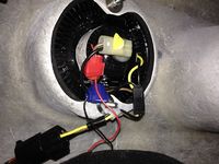
Next up attach the ECU to the reversing lamp to provide the power as and when reverse is engaged


