Difference between revisions of "Reversing sensor"
| (3 intermediate revisions by the same user not shown) | |||
| Line 9: | Line 9: | ||
Think Logically and it is all straight forward. | Think Logically and it is all straight forward. | ||
| − | The kit comes with many parts but I started | + | The kit comes with many parts but I started with the aluminium self adhesive foil strip. It has a connector at one end that you will later attach to the ECU. Start with this in the lowest point of the boot in closest proximity to the battery and then fix the strip right around the boot as low as possible. By the way always a good idea to make sure the inside of the shell is clean and dust free. |
| + | Next up attach the ECU to the reversing lamp to provide the power as and when reverse is engaged. If you haven't already connected the antenna, do it now. Also attach the speaker cable. If you turn the ignition on and engage reverse you should hear an initialisation beep. | ||
| − | + | Now approach the rear of the car slowly, I held out the palm of my hands and test the proximity sensors. You should find the reassuring beeps can be heard. There is a sensitivity dip switch setting and being cautious I set mine to the max. | |
| − | + | So hopefully this is all working but we need to route the speaker cable into the cabin. This being my second installation I found an easier path this time that did not involve removing seats etc. | |
| − | + | First step is to take the speaker cable out through one the the grommets behind the battery location. | |
| − | + | I then ran the cable up along a part of the subframe already exploited for other cables in this way. | |
| + | |||
| + | Having performed a little exploration from inside the cabin I discovered some gap (through foam) that I could poke the cable through that would mean it appearing behind trim above the PAX seat belt (RHD) | ||
| + | |||
| + | Using a cable rod (a wire coat hanger may do) I poked a hole through the foam with the speaker cable attached for it to appear behind the trim above the seat belt. I used a plastic trim tool to lever back the trim and the pull through the speaker cable. I used the gap above the seat belt in the trim to create the exit point. | ||
| + | |||
| + | I reconnected the speaker and stuck it to the panel next to the speaker using the self adhesive tab. | ||
| + | |||
| + | Another test performed to ensure all connections were good and then fixed the ECU using the self adhesive tabs to the luggage compartment floor and refitted the carpets. | ||
| + | |||
| + | Lots of videos on youtube and vendor installation instructions here [http://www.parkingdynamics.co.uk/pd1-rear.pdf] | ||
| + | |||
| + | |||
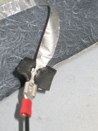
| + | [[File:Antennaconnection.jpg|200px|thumb|left|reversing sensor connector]] | ||
| + | |||
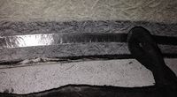
| + | [[File:Reversingantenna.jpg|200px|thumb|left|antenna fixed right around the boot]] | ||
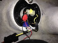
[[File:Rearlightcluster.jpg|200px|thumb|left|red and black ECU cables crimped to the +v and -ve of the reversing lamp]] | [[File:Rearlightcluster.jpg|200px|thumb|left|red and black ECU cables crimped to the +v and -ve of the reversing lamp]] | ||
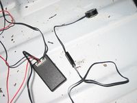
| + | [[File:Testinstall.jpg|200px|thumb|left|Test installation]] | ||
| + | |||
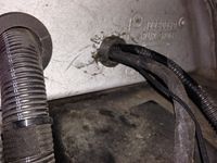
| + | [[File:Cablefromluggage.jpg|200px|thumb|left|speaker cable running into engine bay from grommet behind battery in luggage compartment]] | ||
| + | |||
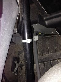
| + | [[File:Speakercablerun.jpg|200px|thumb|left|speaker cable running through engine bay]] | ||
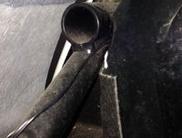
| + | [[File:Throughtocabin.jpg|200px|thumb|left|exit location for speaker cable into compartment]] | ||
| + | [[File:IntertiorTrimaboveseatbelt.jpg|200px|thumb|left|From behind here the cable will appear]] | ||
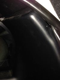
| + | [[File:Outthruseatbelt.jpg|200px|thumb|left|Use the gap above the seat belt loop for the speaker cable exit]] | ||
| − | [[File: | + | [[File:PD1Speaker.jpg|200px|thumb|left|Speaker in situe]] |
Latest revision as of 08:35, 2 June 2014
PD1 Reversing Sensor installation
This is my second installation of the Parking Dynamics PD1 sensor and some of the photographs originate from MY2006 Exige installation and some from a MY2010, but I am guessing nothing serious has changed in the intervening time.
The instructions are very good but if anything make it sound more complex than it is.
Think Logically and it is all straight forward.
The kit comes with many parts but I started with the aluminium self adhesive foil strip. It has a connector at one end that you will later attach to the ECU. Start with this in the lowest point of the boot in closest proximity to the battery and then fix the strip right around the boot as low as possible. By the way always a good idea to make sure the inside of the shell is clean and dust free.
Next up attach the ECU to the reversing lamp to provide the power as and when reverse is engaged. If you haven't already connected the antenna, do it now. Also attach the speaker cable. If you turn the ignition on and engage reverse you should hear an initialisation beep.
Now approach the rear of the car slowly, I held out the palm of my hands and test the proximity sensors. You should find the reassuring beeps can be heard. There is a sensitivity dip switch setting and being cautious I set mine to the max.
So hopefully this is all working but we need to route the speaker cable into the cabin. This being my second installation I found an easier path this time that did not involve removing seats etc.
First step is to take the speaker cable out through one the the grommets behind the battery location.
I then ran the cable up along a part of the subframe already exploited for other cables in this way.
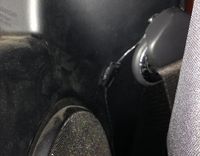
Having performed a little exploration from inside the cabin I discovered some gap (through foam) that I could poke the cable through that would mean it appearing behind trim above the PAX seat belt (RHD)
Using a cable rod (a wire coat hanger may do) I poked a hole through the foam with the speaker cable attached for it to appear behind the trim above the seat belt. I used a plastic trim tool to lever back the trim and the pull through the speaker cable. I used the gap above the seat belt in the trim to create the exit point.
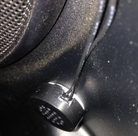
I reconnected the speaker and stuck it to the panel next to the speaker using the self adhesive tab.
Another test performed to ensure all connections were good and then fixed the ECU using the self adhesive tabs to the luggage compartment floor and refitted the carpets.
Lots of videos on youtube and vendor installation instructions here [1]
