Uploads by Andrew S
Jump to navigation
Jump to search
This special page shows all uploaded files.
| Date | Name | Thumbnail | Size | Description | Versions |
|---|---|---|---|---|---|
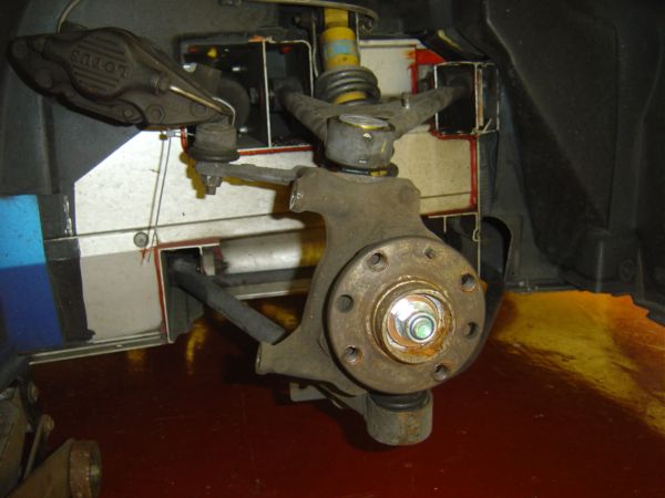
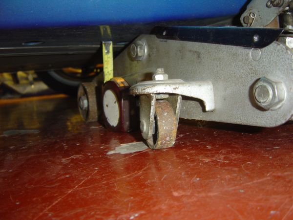
| 09:40, 18 June 2006 | 2. Measuring Lower Wishbone Height.JPG (file) |  |
32 KB | How to change a Ball Joint and a Damper This procedure details how to change the offside lower front ball joint and damper assembly. The nearside front is an identical procedure and the upper front ball joints follow a similar procedure. The rear ball j | 1 |
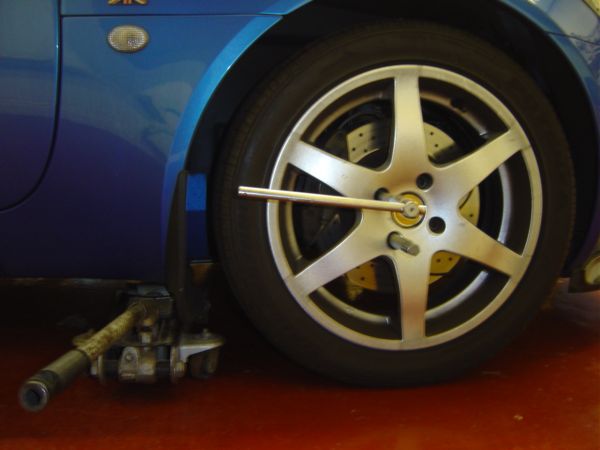
| 09:42, 18 June 2006 | 3. Loosening Road Wheel Bolts.JPG (file) |  |
36 KB | Step 2. Loosen the bolts on the road wheel | 1 |
| 09:48, 18 June 2006 | 4. Road Wheel Removed.JPG (file) |  |
44 KB | Step 3. Jack up the car on the front jacking point using a trolley jack and remove the front road wheel. | 1 |
| 09:48, 18 June 2006 | 5. Removing Brake Pipe Clamp.JPG (file) |  |
44 KB | Step 4. Remove the brake pipe clamp. | 1 |
| 09:49, 18 June 2006 | 6. Removing Front Brake Caliper.JPG (file) |  |
45 KB | Step 5. Remove the brake caliper using an 8mm hex driver or allen key. | 1 |
| 09:50, 18 June 2006 | 7. Securing Front Brake Caliper.JPG (file) |  |
42 KB | Step 6. Secure the brake caliper so that it does not get in the way of removing the ball joint. Ensure that the brake line is not under strain and taking the weight of the caliper. You may wish to use a cable tie to secure the caliper out of the way. | 1 |
| 09:50, 18 June 2006 | 8. Removing Lower Ball Joint Nut.JPG (file) |  |
44 KB | Step 7. Remove the ball joint nut . Use a 19mm ring/open ended spanner for the lower ball joint. You need to start with the ring end and transfer to the open end after winding the nut half the way up, otherwise the ring spanner will get stuck between the | 1 |
| 09:51, 18 June 2006 | 9. Splitting Lower Ball Joint.JPG (file) |  |
43 KB | Step 8. Split the ball joint from the hub carrier. You may wish to use a fork splitter with a few hard hits with a club hammer. Alternatively you could use a scissor splitter. | 1 |
| 09:52, 18 June 2006 | 10. Lower Ball Joint Split From Hub Carrier.JPG (file) |  |
46 KB | Step 9. When the ball joint is split from the hub carrier move carrier out of the way. You could use a trolley jack handle as a prop for the hub carrier under the track rod end bolt. Remove the ball joint rubber dust cover. | 1 |
| 09:52, 18 June 2006 | 11. Steering Wheel Set To Full Lock.JPG (file) |  |
45 KB | Step 10. Turn the steering wheel to full lock to move the hub carrier out of the way, so you can fit a ball joint removal tool. | 1 |
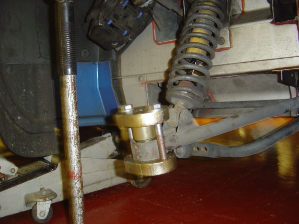
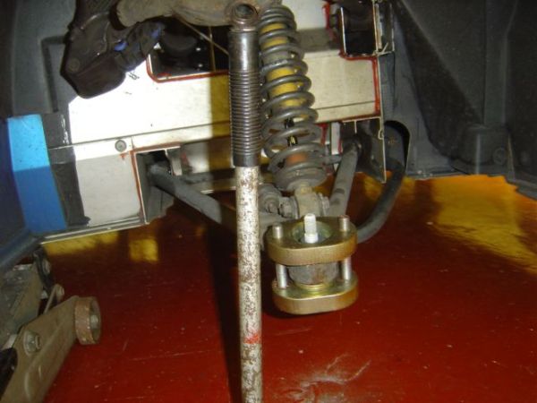
| 09:53, 18 June 2006 | 12. Ball Joint Removal Tool Assembled.JPG (file) |  |
48 KB | Step 11. Assemble the ball joint removal tool and make sure that you coat the bolt threads with plenty of copper grease. This is an Elise Parts ball joint removal tool. | 1 |
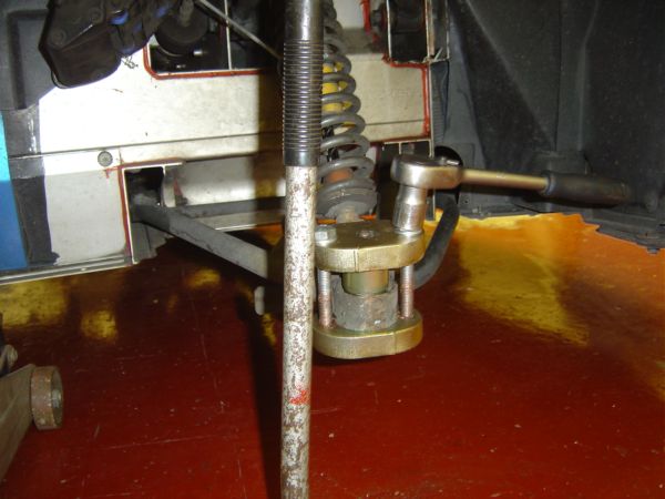
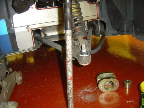
| 09:54, 18 June 2006 | 13. Removing Ball Joint.JPG (file) |  |
46 KB | Step 12. Using a 19mm socket/ratchet , tighten the bolts 2 turns each keeping them even. | 1 |
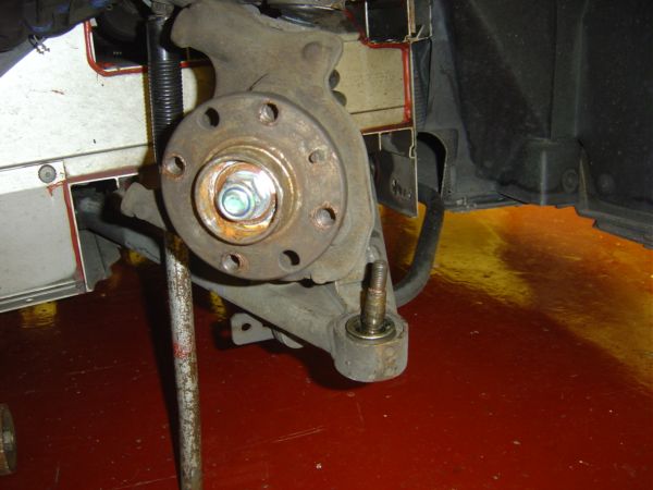
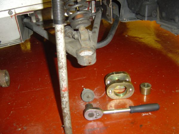
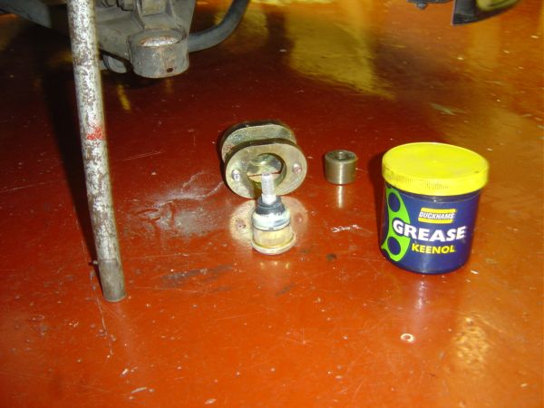
| 09:54, 18 June 2006 | 14. Ball Joint Removed.JPG (file) |  |
48 KB | Step 13. The ball joint pops out very easily. | 1 |
| 09:55, 18 June 2006 | 15. Greasing New Ball Joint Rubber.JPG (file) |  |
47 KB | Step 14. You may wish to put new ball joints in the freezer for a day or two. This ensures an easy fit into the wishbone. Grease the rubber dust cover so that it does not snag. | 1 |
| 09:56, 18 June 2006 | 16. Fitting New Ball Joint.JPG (file) |  |
47 KB | Step 15. Hand fit the new ball joint into the wishbone. It should go in easily if it is frozen as it will be slightly contracted. | 1 |
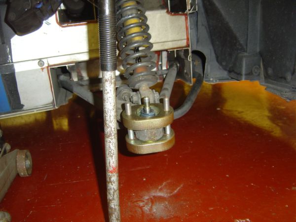
| 09:56, 18 June 2006 | 17. Ball Joint Assembly Tool.JPG (file) |  |
44 KB | Step 16. Fit the ball joint assembly tool and hand tighten the bolts making sure everything is evenly spaced. | 1 |
| 09:57, 18 June 2006 | 18. Ball Joint Fitted.JPG (file) |  |
46 KB | Step 17. Tighten the bolts two turns at a time until the ball joint is seated. The heat created during fitting will defrost the ball joint. | 1 |
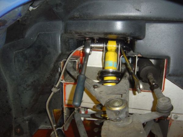
| 09:58, 18 June 2006 | 19. Removing Lower Shock Mount.JPG (file) |  |
47 KB | Step 18. Now it is time to remove the lower damper bolt using a 17mm socket and open/ring spanner. | 1 |
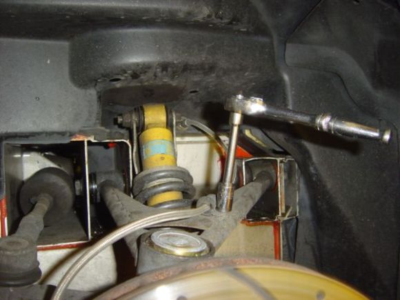
| 09:58, 18 June 2006 | 20. Removing Upper Shock Mount.JPG (file) |  |
48 KB | Step 19. Followed by the upper damper bolt. You will notice that the brake hose is straining in this photograph and I had to reposition the caliper so that the strain was removed from the hose. | 1 |
| 09:59, 18 June 2006 | 21. Shock Assembly Removed.JPG (file) |  |
43 KB | Step 20. The assembly is now off the car and is waiting for the spring to be removed. | 1 |
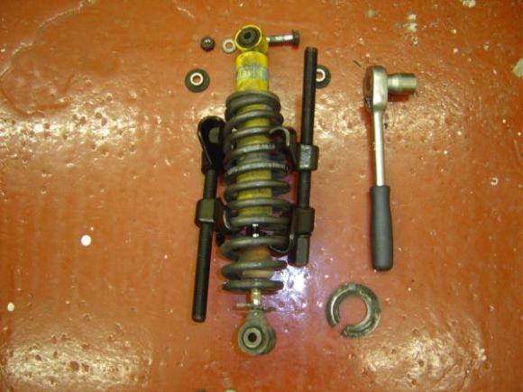
| 09:59, 18 June 2006 | 22. Removing Spring From Damper.JPG (file) |  |
48 KB | Step 21. In this photograph, the spring is compressed using compressors designed for bigger diameter springs. These work o.k. but more appropriate spring compressors can be purchased. Once the spring is compressed enough the bottom spring plate can be re | 1 |
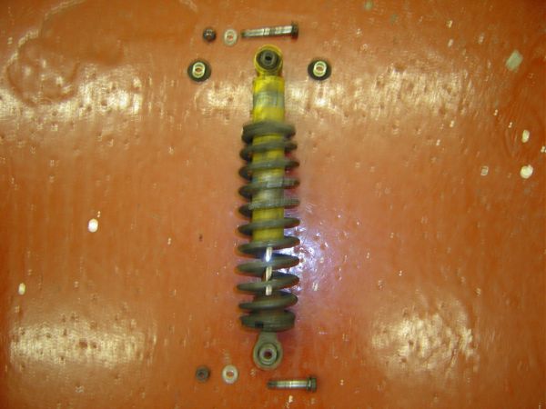
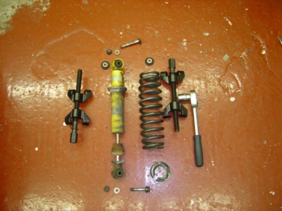
| 10:00, 18 June 2006 | 23. Spring Removed From Damper.JPG (file) |  |
46 KB | Step 22. If you use oversize spring compressors you will need to unclamp the compressors to remove the spring from the damper. | 1 |
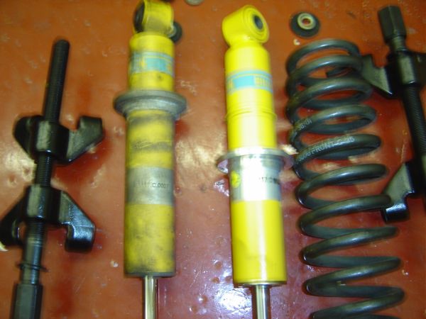
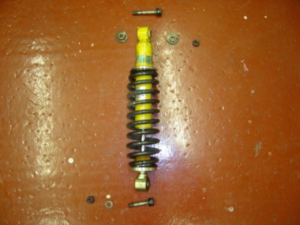
| 10:01, 18 June 2006 | 24. Spring Ready To Be Fitted To New Damper.JPG (file) |  |
48 KB | Step 23. Here is the new damper alongside the old one ready for the spring to be assembled. | 1 |
| 10:02, 18 June 2006 | 25. Fitting Spring To New Damper.JPG (file) |  |
48 KB | Step 24. Fit the spring to the new damper using the spring compressors. | 1 |
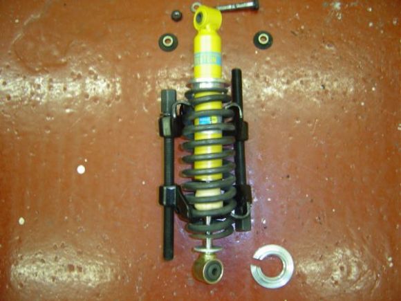
| 10:02, 18 June 2006 | 26. Spring Compressed On New Damper.JPG (file) |  |
46 KB | Step 25. Here is the spring compressed on the new damper. | 1 |
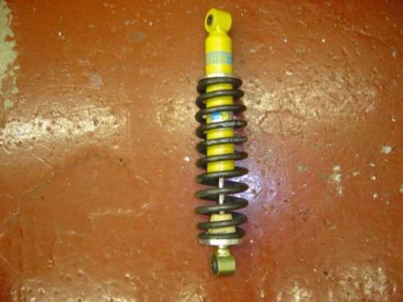
| 10:03, 18 June 2006 | 27. Spring Fitted To New Damper.JPG (file) |  |
45 KB | Step 26. Here is the spring fitted to the damper. Take care to ensure the end of the bottom part of the spring is 180 degrees away from the slot in the bottom spring plate. | 1 |
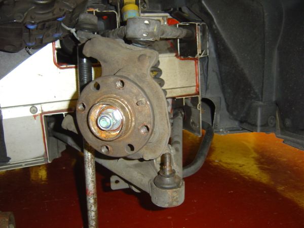
| 10:04, 18 June 2006 | 28. Lowering Jack To Normal Ride Height.JPG (file) |  |
47 KB | Step 27. Refit the damper assembly and grease the upper bushes. Do not tighten the upper or lower bolts at this stage. Lower the jack supporting the car to it’s minimum position and jack the suspension to the measurement at step 1. This is to ensure the | 1 |
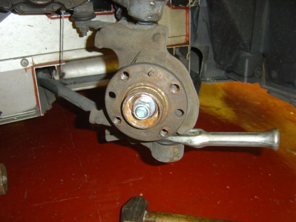
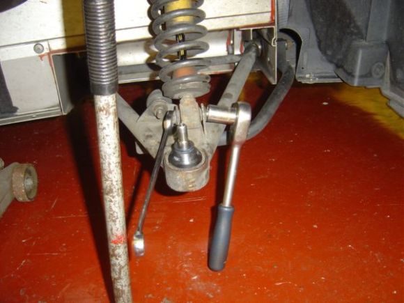
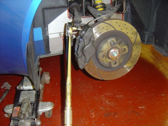
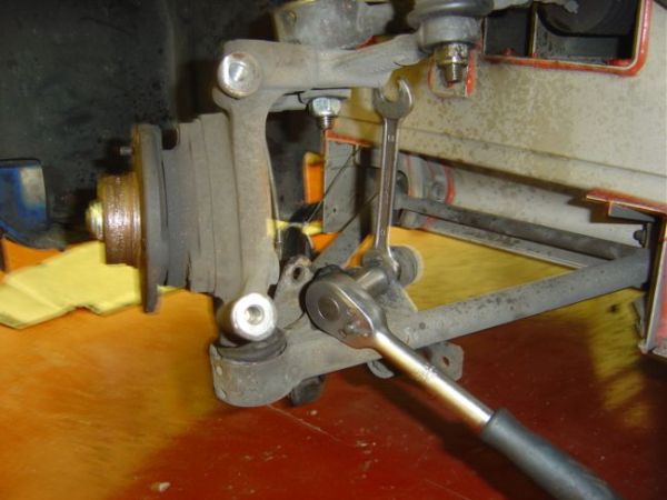
| 10:05, 18 June 2006 | 30. Tighteneing Lower Ball Joint.JPG (file) |  |
46 KB | Step 28. With the suspension under compression tighten the lower ball joint nut to 45NM. If you only have a basic tool kit you will not be able to use a 19mm socket and torque wrench because the hub carrier will be in the way, so you will need to estimate | 1 |
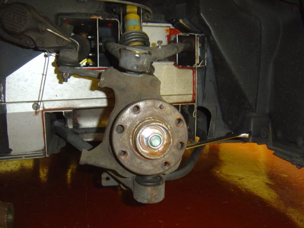
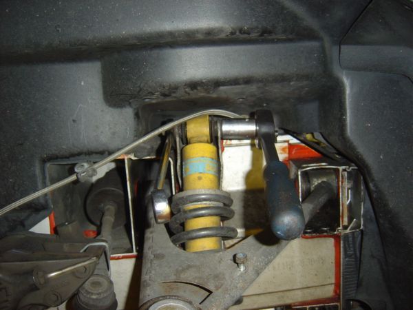
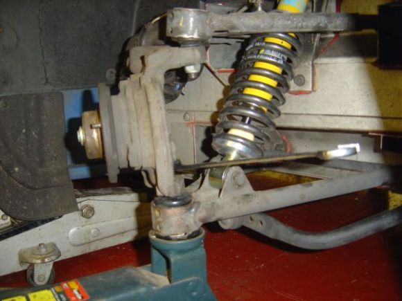
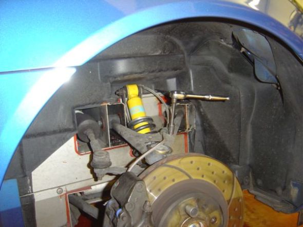
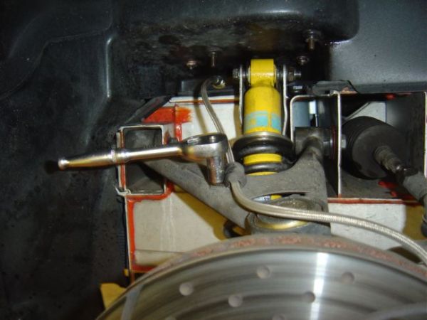
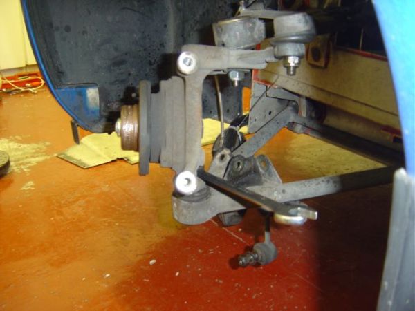
| 10:05, 18 June 2006 | 31. Damper And Lower Ball Joint Fitted.JPG (file) |  |
42 KB | Step 29. The damper and lower ball joint are now fitted. Note that the caliper is now repositioned to alleviate the straining on the brake pipe back in step 19. | 1 |
| 10:06, 18 June 2006 | 32. Measuring Brake DiscThickness.JPG (file) |  |
49 KB | Step 30. You can measure the thickness of your brake rotor using a micrometer. My measurement was 24.4mm which should last until my next pad change. | 1 |
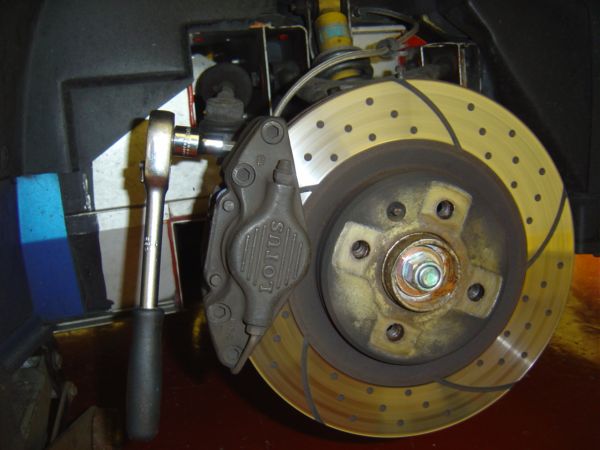
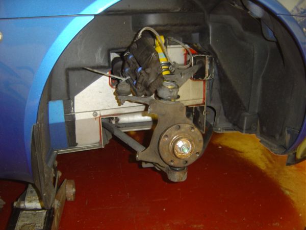
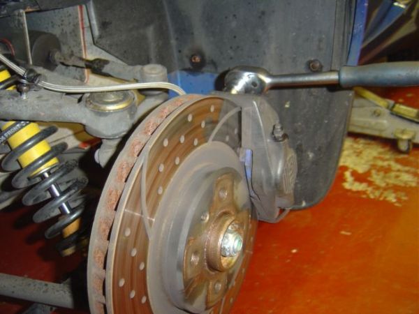
| 10:07, 18 June 2006 | 33. Refitting Brake Caliper.JPG (file) |  |
46 KB | Step 31. Refit the brake caliper and torque down to 45NM (I don’t use retaining compound on these bolts as they are frequently removed). | 1 |
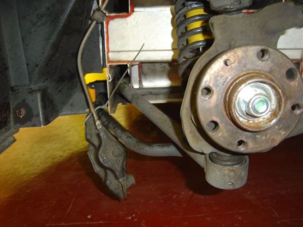
| 10:07, 18 June 2006 | 34. Securing Brake Pipe.JPG (file) |  |
46 KB | Step 32. Secure the brake pipe to the top wishbone. | 1 |
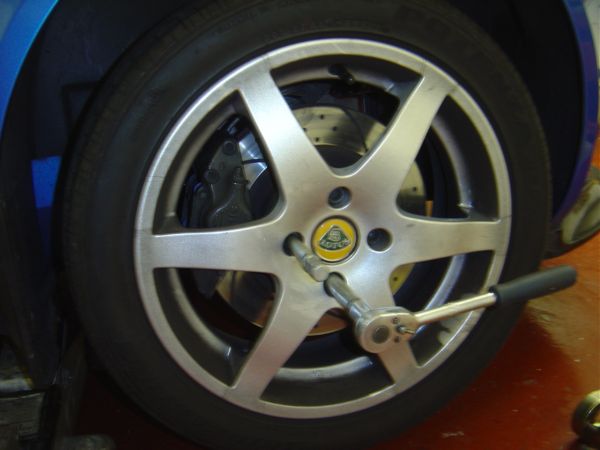
| 10:08, 18 June 2006 | 35. Tightening Wheel Bolts.JPG (file) |  |
38 KB | Step 33. Refit the road wheel and nip up the wheel bolts. Check that there is no side to side play by trying to rock the wheel at a quarter to three. | 1 |
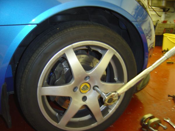
| 10:08, 18 June 2006 | 36 Torque Wheel Bolts.JPG (file) |  |
46 KB | Step 34. Lower car to the ground and torque wheel bolts to 105NM. Depress brake pedal a few times to get the pressure back. | 1 |
| 10:09, 18 June 2006 | 37. Leaking Damper.JPG (file) |  |
38 KB | This is an example of a badly leaking damper. | 1 |
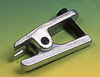
| 10:10, 18 June 2006 | 39. Scissor Type Ball Joint Splitter.jpg (file) |  |
3 KB | Here is an alternative ball joint splitter | 1 |
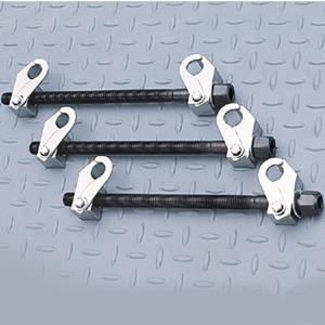
| 10:10, 18 June 2006 | 38. Alternative Coil Spring Compressor.jpg (file) |  |
13 KB | Here are alternative coil spring compressors | 1 |
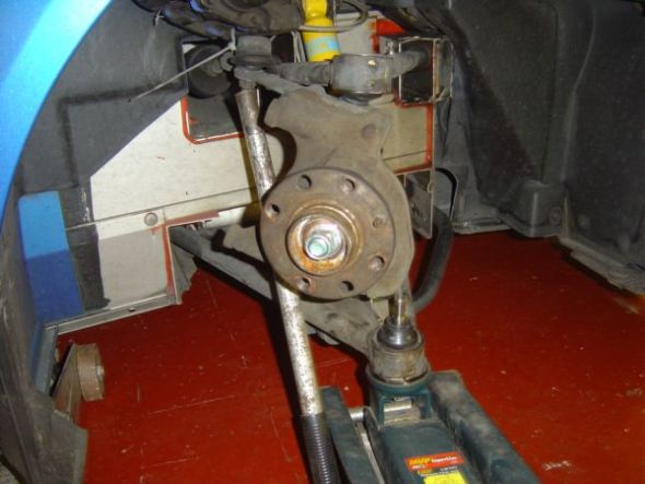
| 13:03, 18 June 2006 | 29. Jacking Lower Wishbone To Ride Height.JPG (file) |  |
45 KB | Step 27. Refit the damper assembly and grease the upper bushes. Do not tighten the upper or lower bolts at this stage. Lower the jack supporting the car to it’s minimum position and jack the suspension to the measurement at step 1. This is to ensure the | 1 |
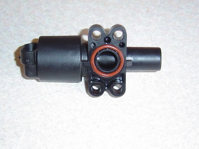
| 14:03, 18 June 2006 | S2 K Series IACV.JPG (file) |  |
47 KB | The S2 K Series IACV is part number A117E6069S | 1 |
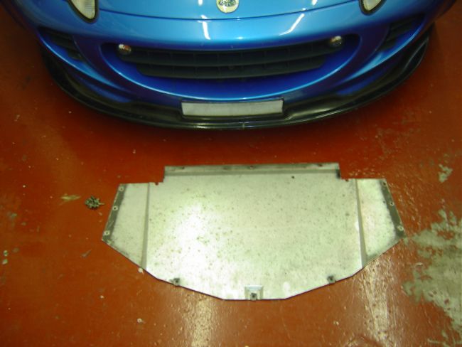
| 22:51, 31 July 2006 | 1 Remove Front Under Tray.JPG (file) |  |
46 KB | 1 | |
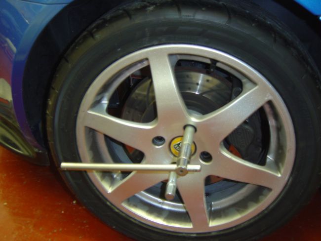
| 22:56, 31 July 2006 | 2 Loosen Bolts on Road Wheel.JPG (file) |  |
45 KB | 1 | |
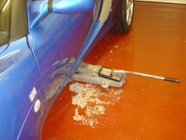
| 22:57, 31 July 2006 | 3 Lift Car Using Rear Jacking Point.JPG (file) |  |
43 KB | 1 | |
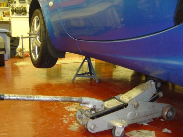
| 22:57, 31 July 2006 | 4 Use Fixed Support Under Front Jacking Point.JPG (file) |  |
46 KB | 1 | |
| 22:57, 31 July 2006 | 5 Remove Brake Pipe Clamp.JPG (file) |  |
44 KB | 1 | |
| 22:57, 31 July 2006 | 6 Remove Brake Caliper.JPG (file) |  |
49 KB | 1 | |
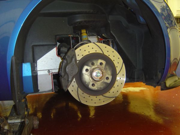
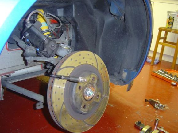
| 22:58, 31 July 2006 | 7 Remove Brake Disc.JPG (file) |  |
45 KB | 1 | |
| 22:58, 31 July 2006 | 8a Remove Damper Assembly.JPG (file) |  |
47 KB | 1 | |
| 22:58, 31 July 2006 | 8b Damper Assembly Removed.JPG (file) |  |
44 KB | 1 | |
| 22:59, 31 July 2006 | 9 Remove Drop Link.JPG (file) |  |
46 KB | 1 | |
| 22:59, 31 July 2006 | 10 Remove Upper & Lower Ball Joint Nuts.JPG (file) |  |
45 KB | 1 |