Difference between revisions of "VVC Information"
hbaumhardt (talk | contribs) |
Hbaumhardt (talk | contribs) |
||
| (30 intermediate revisions by 5 users not shown) | |||
| Line 1: | Line 1: | ||
| − | The S1 143bhp EU2 VVC is controlled by the | + | The Elise S1 111S 143bhp EU2 VVC is controlled by the MEMS 2J ECU common with the early VVC MGFs |
| − | The S2 156bhp EU3 VVC is controlled by the Lotus K4 ECU ( | + | The Elise S2 111S 156bhp EU3 VVC is controlled by the Lotus K4 ECU A117M0109F (which looks the same as the MEMS 3 but is *NOT*). |
| + | |||
| + | ==EU2 & EU3 Differences== | ||
| + | |||
| + | The mechanicals which are different from the EU3 to EU2 engine: | ||
| + | |||
| + | 1. 52mm TB as standard (EU2 48mm) | ||
| + | |||
| + | 2. Wasted spark coil packs on top of the plugs (EU2 under induction) | ||
| + | |||
| + | 3. KTM plate oil/water cooler under the induction (EU2 none) | ||
| + | |||
| + | 4. Dark blue 192cc/min injectors (EU2 cream 218cc/min) | ||
| + | |||
| + | 5. TF160 pistons with marginally higher compression and expanded ring belt to strengthen ring lands, indentifiable by '160' engraved on the crown (EU2 standard pistons) | ||
| + | |||
| + | 6. Double tang conrods (EU2 single tang) | ||
| + | |||
| + | 7. Machining of the head around the inlet and exhaust valves (triple-angle valve seats) both in the valve throats and combustion chamber to improve low lift flow | ||
| + | |||
| + | 8. VVC control connectors are differnt colours and have different keyways | ||
| + | |||
| + | 9. IACV MDQ100170 is PWM (EU2 is Stepper) | ||
| + | |||
| + | 10. Cam Position Sensor NSC000010 may have a longer pickup (EU2 is NSC100380) | ||
==VVC Failure Modes== | ==VVC Failure Modes== | ||
| − | ECT Sensor | + | ECT Sensor low/error limits to 6K RPM |
| − | MAP Sensor | + | MAP Sensor error limits to 6K RPM |
| − | VVC | + | VVC Oil Temp Sensor low/error limites to 6K RPM |
| − | + | VVC Solenoid low resistance (should be 6.6 to 8.8 Ohms) limits to 5.5K RPM | |
| + | ECU VVC control circuit fried (from wrong battery polarity) limits to 5.5K RPM | ||
| + | |||
| + | Cam Position Sensor limits to 5.5K RPM (The VVC CPS is NSC000010 variable reluctance, different to the standard K16 Hall effect) | ||
| + | |||
| + | |||
| + | Excellent write up on the S1 EU2 VVC MEMS 2J logic and failure modes here * http://www.mgfcar.de/library/ENGINE_MANAGEMENT_SYSTEM_VVC_MEMS_2J.htm | ||
| + | |||
| + | Excellent write up on the EU3 VVC MEMS 3 logic (which the S2 K4 is based on) and failure modes here * | ||
| + | http://www.mgfcar.de/library/ENGINE_MANAGEMENT_SYSTEM_%20MPi_VVC_MEMS_3.htm | ||
| − | |||
Note: Connecting the battery on wrong polarity can blow the K4 ECU VVC control circut, as can running with a low resistance solenoid. Lotus issued a service note on this. | Note: Connecting the battery on wrong polarity can blow the K4 ECU VVC control circut, as can running with a low resistance solenoid. Lotus issued a service note on this. | ||
| − | + | http://wiki.seloc.org/images/a/a2/VVC_Solenoid_SB.jpg | |
==Lotus S2 K4 ECU VVC Connections== | ==Lotus S2 K4 ECU VVC Connections== | ||
| Line 39: | Line 71: | ||
The S1 connector order is LEFT < Blue - Black - Brown > RIGHT VVC Actuator | The S1 connector order is LEFT < Blue - Black - Brown > RIGHT VVC Actuator | ||
| − | + | [img]http://gallery.seloc.org/albums/userpics/24232/S2_VVC_Engine_Sensors.JPG[/img] | |
==Lotus S2 K4 ECU VVC DTC Codes== | ==Lotus S2 K4 ECU VVC DTC Codes== | ||
| Line 48: | Line 80: | ||
|- | |- | ||
| P1336 || S2 Crankshaft Position System Variation Not Learned || | | P1336 || S2 Crankshaft Position System Variation Not Learned || | ||
| + | |- | ||
| + | | P1400 || S2 Fan 1 Relay Short || | ||
| + | |- | ||
| + | | P1401 || S2 Fan 1 Relay Open || | ||
| + | |- | ||
| + | | P1402 || S2 Fan 2 Relay Short [unverified] || | ||
| + | |- | ||
| + | | P1403 || S2 Fan 2 Relay Open [unverified] || | ||
| + | |- | ||
| + | | P1470 || S2 Coolant Recirculation Relay Open [unverified] || | ||
|- | |- | ||
| P1480 || S2 Exhaust flap relay open || | | P1480 || S2 Exhaust flap relay open || | ||
| Line 66: | Line 108: | ||
|- | |- | ||
|} | |} | ||
| + | |||
| + | ==VVC Timing Information== | ||
| + | |||
| + | Timing of VVC, text by Dave Andrews (DVA Power), Pictures and additional text by Rob Clarke | ||
| + | |||
| + | Ok...first off we need a cam carrier with the inlet nearest to me so the front of the engine is on my left. | ||
| + | |||
| + | [[Image:vvcrebuild-step1.jpg]] | ||
| + | |||
| + | Fitting the front VVC mechanism to the cam carrier, at the moment this is just held on with two bolt so it doesn’t fall off and fall apart. | ||
| + | |||
| + | [[Image:vvcrebuild-step2.jpg]] | ||
| + | |||
| + | Turn the inner rotating part of the mech. so that the toothed rack on the outer rotor moves in a clockwise direction and the slot in the rotor lines up with the slot machined in the outer support ring of the mech casing at the top centre (as viewed). | ||
| + | |||
| + | [[Image:vvcrebuild-step3.jpg]] | ||
| + | |||
| + | At this point the teeth on the rotor should start pretty much level with the cam ladder surface and extend down and below the surface of the rack radially, effectively from the 3 O’clock position to the 7 O’clock position as viewed from the front of the ladder. The start of the rotors toothed rack should be clearly visible through the break in the casing support ring where the synch. shaft will fit. | ||
| + | |||
| + | [[Image:vvcrebuild-step4.jpg]] | ||
| + | |||
| + | Support the VVC mech. with your hand and remove the two bolts holding the mech. to the ladder, do not let the mech fall away or disengage from the cam. Rotate the mech. slighty anti-clockwise so that the slot which accepts the synch shaft moves upwards a little away from the ladder. Take the synch shaft and enmesh the front end (this has two tooth pinions) into the teeth on the mechs rotor. Rotate the VVC mech back into its correct position and this should bring the synch shaft down into it’s correct position nestling in its bearings. Replace the bolts holding the VVC mech. to the ladder and do them up nearly tight. Rotate the synch shaft in an anti clockwise direction until the pinion teeth meet the end of the toothed track on the VVC mech. rotor and the shaft will turn no more. | ||
| + | |||
| + | [[Image:vvcrebuild-step5.jpg]] | ||
| + | |||
| + | At this point the slot on the rotor and the slot on the mech. casting at the top centre should be pretty much in line. | ||
| + | |||
| + | [[Image:vvcrebuild-step6.jpg]] | ||
| + | |||
| + | Take the rear VVC mech/cam and rotate the inner rotor in an anti-clockwise direction until the slot in the rotor and the slot in the mech housing at the top are in line, when this is done the teeth on the rotor should occupy the 3 O’clock to 7 O’clock positions as with the front mech and it should be a mirror image of the front mech with the end of the teetyh track clearly visible at the point where the synch shaft will fit. | ||
| + | |||
| + | Now fit the VVC rear mech/cam to the ladder while fitting the synch shaft rear end to the teeth track on the mech, There is a bit of a knack to making sure the synch shaft enmeshes in the correct tooth on the inner rotor. Make sure the cam is sitting correctly in its bearings and the VVC mech. is aligned with its bolt holes and then fix the rear VVC mech to the ladder with two bolts and ensure these are nearly tight as with the front mech. Rotate the synch shaft in an anti-clockwise direction until it will not turn any more and ensure that the teeth on each pinion at either end have reached the last tooth on the VVC mech rotor, if they are not exactly in synch then undo the bolts on the rear mech, rotate this anti clockwise a little until the synch shaft can be disengaged from the toothed track and re-synch the track and pinion, then re-seat the mech and do the bolts up. Continue until the two mechs are in synch. with one another and effectively mirror images and ensure the synch shaft is rotated fully anti-clockwise until it locks against the ends of the toothed tracks. | ||
| + | |||
| + | [[Image:vvcrebuild-step7.jpg]] | ||
| + | |||
| + | If the cams are installed correctly the lobs will be in these positions | ||
| + | |||
| + | [[Image:vvcrebuild-step8.jpg]] | ||
| + | |||
| + | Once the cam ladder is on the head you can check the timing marks, with everything lined up you should be able to see a semi-circle in the 6mm hole in the cam carrier like this | ||
| + | |||
| + | Front cam - | ||
| + | |||
| + | [[Image:Headbuild-vvctimingrear.jpg]] | ||
| + | |||
| + | Rear cam – | ||
| + | |||
| + | [[Image:Headbuild-vvctimingfront.jpg]] | ||
| + | |||
| + | ==VVC Mechanisms Strip down== | ||
| + | |||
| + | First off here are most of the bits inside of the VVC mechanism housing, I say most because there is a bearing pressed into the housing that doesn’t come out. In this picture you can see the cam, two “plates” with caged bearings and 4 “slidey things” and finally an inner sleeve for want a better word which has the teeth for the VVC sync shaft. | ||
| + | |||
| + | [[Image:Vvc-interntals.jpg]] | ||
| + | |||
| + | At this point I have to point out that it was very important to mark every item if disassembling as the “slidey” bits do wear a little and if not fitted into the same place on reassembly they don’t slide properly. Same goes for the plates. | ||
| + | |||
| + | With all the bits removed from the mechanism I gave it a bit of a clean out then applied some fresh engine oil into it. Added the outer sleeve to the housing ready for the first plate. | ||
| + | |||
| + | [[Image:VVC-strippedmech-Step1.jpg]] | ||
| + | |||
| + | First insert the first plate, this goes in with the lip at the bottom | ||
| + | |||
| + | [[Image:VVC-strippedmech-Step2.jpg]] | ||
| + | |||
| + | Insert the bearing cage, this sits around the plate. Add the two slidey blocks, making sure they are in the right place. They should fit “nice” i.e you don’t need to force them in. One of the slidey blocks sits on one of the pins that is in the bottom of the housing | ||
| + | |||
| + | [[Image:VVC-strippedmech-Step3.jpg]] | ||
| + | |||
| + | Taking the next plate (lip on top this time) and fitting the bearing cage before fitting both into the housing, noting that the large hole allows access to the slidey block on the lower plate that didn’t have the pin in. (this will be a locating hole for one of the cam pins) One of slidey blocks goes over the second pin that is fixed to the bottom of the housing. The last slidey block is ready to take the second pin from the cam. | ||
| + | |||
| + | [[Image:VVC-strippedmech-Step4.jpg]] | ||
| + | |||
| + | Now the two pins on the cam locate into the to slidey blocks (one on the lower plate and one on the upper one). Its now ready for installation | ||
| + | |||
| + | [[Image:VVC-strippedmech-Step5.jpg]] | ||
| + | |||
| + | ==VVC Hydraulic Control Unit== | ||
| + | |||
| + | HCU is oil pressure controlled, the piston operates the VVC sync shaft which inturn changes the cam timing. | ||
| + | |||
| + | In a few bits | ||
| + | |||
| + | [[Image:HCU-Exploded.jpg]] | ||
| + | |||
| + | VVC gaskets, this is available from Rimmer Bros or PTP | ||
| + | |||
| + | [[Image:VVCgaskets.jpg]] | ||
| + | |||
| + | HCU piston assembled | ||
| + | |||
| + | [[Image:VVC-HCU.jpg]] | ||
| + | |||
| + | The heart of the control mechanism of the HCU is the “spool valve”, this looks like a pipe which is full of holes. | ||
| + | |||
| + | [[Image:VVC-internal.jpg]] | ||
| Line 85: | Line 223: | ||
[[Category:S1]] | [[Category:S1]] | ||
[[Category:S2]] | [[Category:S2]] | ||
| + | |||
| + | |||
| + | ==Fitting an EU2 VVC Engine to a non-VVC S1 Elise== | ||
| + | Lotus didnt make any changes to the car's wiring loom between their standard 120bhp S1 and the 143bhp VVC powered 111S. This means that you can easily fit an EU2 VVC K-Series engine (eg. from an MGF) and run it using the Rover MEMS J2 ECU. All you'll need is a donor VVC engine, engine loom and a matching Lucas 5AS module (sits behind the Stack dashboard) to make the swap. | ||
Latest revision as of 17:53, 19 September 2011
The Elise S1 111S 143bhp EU2 VVC is controlled by the MEMS 2J ECU common with the early VVC MGFs
The Elise S2 111S 156bhp EU3 VVC is controlled by the Lotus K4 ECU A117M0109F (which looks the same as the MEMS 3 but is *NOT*).
EU2 & EU3 Differences
The mechanicals which are different from the EU3 to EU2 engine:
1. 52mm TB as standard (EU2 48mm)
2. Wasted spark coil packs on top of the plugs (EU2 under induction)
3. KTM plate oil/water cooler under the induction (EU2 none)
4. Dark blue 192cc/min injectors (EU2 cream 218cc/min)
5. TF160 pistons with marginally higher compression and expanded ring belt to strengthen ring lands, indentifiable by '160' engraved on the crown (EU2 standard pistons)
6. Double tang conrods (EU2 single tang)
7. Machining of the head around the inlet and exhaust valves (triple-angle valve seats) both in the valve throats and combustion chamber to improve low lift flow
8. VVC control connectors are differnt colours and have different keyways
9. IACV MDQ100170 is PWM (EU2 is Stepper)
10. Cam Position Sensor NSC000010 may have a longer pickup (EU2 is NSC100380)
VVC Failure Modes
ECT Sensor low/error limits to 6K RPM
MAP Sensor error limits to 6K RPM
VVC Oil Temp Sensor low/error limites to 6K RPM
VVC Solenoid low resistance (should be 6.6 to 8.8 Ohms) limits to 5.5K RPM
ECU VVC control circuit fried (from wrong battery polarity) limits to 5.5K RPM
Cam Position Sensor limits to 5.5K RPM (The VVC CPS is NSC000010 variable reluctance, different to the standard K16 Hall effect)
Excellent write up on the S1 EU2 VVC MEMS 2J logic and failure modes here * http://www.mgfcar.de/library/ENGINE_MANAGEMENT_SYSTEM_VVC_MEMS_2J.htm
Excellent write up on the EU3 VVC MEMS 3 logic (which the S2 K4 is based on) and failure modes here * http://www.mgfcar.de/library/ENGINE_MANAGEMENT_SYSTEM_%20MPi_VVC_MEMS_3.htm
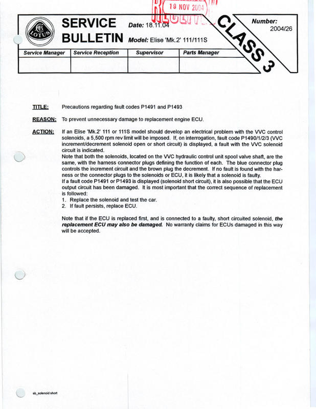
Note: Connecting the battery on wrong polarity can blow the K4 ECU VVC control circut, as can running with a low resistance solenoid. Lotus issued a service note on this.
http://wiki.seloc.org/images/a/a2/VVC_Solenoid_SB.jpg
Lotus S2 K4 ECU VVC Connections
| K4 Pin | Wire | Function | Connector |
| 06 | Blue | VVC Oil Temp Earth | BLACK |
| 10 | Green Orange | VVC Oil Temp Signal | BLACK |
| 12 | Black Yellow | VVC Decriment | BLUE |
| 49 | Brown Black | VVC Increment | BROWN |
The S2 Connector order is LEFT < Blue - Brown - Black > RIGHT VVC Actuator
The S1 connector order is LEFT < Blue - Black - Brown > RIGHT VVC Actuator
[img]http://gallery.seloc.org/albums/userpics/24232/S2_VVC_Engine_Sensors.JPG[/img]
Lotus S2 K4 ECU VVC DTC Codes
The S2 ECU is ODB2 compliant (ISO9141/KWP2000) so can be read by most scantools. Of course the S1 MEMS isn't OBD2 so no idea what that spits out ...
| Code | Description | |
| P1336 | S2 Crankshaft Position System Variation Not Learned | |
| P1400 | S2 Fan 1 Relay Short | |
| P1401 | S2 Fan 1 Relay Open | |
| P1402 | S2 Fan 2 Relay Short [unverified] | |
| P1403 | S2 Fan 2 Relay Open [unverified] | |
| P1470 | S2 Coolant Recirculation Relay Open [unverified] | |
| P1480 | S2 Exhaust flap relay open | |
| P1481 | S2 Exhaust flap short circuit | |
| P1490 | S2 VVC brown increment solenoid open circuit (Black Yellow) | |
| P1491 | S2 VVC brown increment solenoid short circuit (Black Yellow) | |
| P1492 | S2 VVC blue decrement solenoid open circuit (Black Brown) | |
| P1493 | S2 VVC blue decrement solenoid Short circuit (Black Brown) | |
| P1494 | S2 VVC black oil temp sensor LOW open circuit (Green Orange + Blue) | |
| P1495 | S2 VVC black oil temp sensor HIGH short circuit (Green Orange + Blue) |
VVC Timing Information
Timing of VVC, text by Dave Andrews (DVA Power), Pictures and additional text by Rob Clarke
Ok...first off we need a cam carrier with the inlet nearest to me so the front of the engine is on my left.

Fitting the front VVC mechanism to the cam carrier, at the moment this is just held on with two bolt so it doesn’t fall off and fall apart.

Turn the inner rotating part of the mech. so that the toothed rack on the outer rotor moves in a clockwise direction and the slot in the rotor lines up with the slot machined in the outer support ring of the mech casing at the top centre (as viewed).

At this point the teeth on the rotor should start pretty much level with the cam ladder surface and extend down and below the surface of the rack radially, effectively from the 3 O’clock position to the 7 O’clock position as viewed from the front of the ladder. The start of the rotors toothed rack should be clearly visible through the break in the casing support ring where the synch. shaft will fit.

Support the VVC mech. with your hand and remove the two bolts holding the mech. to the ladder, do not let the mech fall away or disengage from the cam. Rotate the mech. slighty anti-clockwise so that the slot which accepts the synch shaft moves upwards a little away from the ladder. Take the synch shaft and enmesh the front end (this has two tooth pinions) into the teeth on the mechs rotor. Rotate the VVC mech back into its correct position and this should bring the synch shaft down into it’s correct position nestling in its bearings. Replace the bolts holding the VVC mech. to the ladder and do them up nearly tight. Rotate the synch shaft in an anti clockwise direction until the pinion teeth meet the end of the toothed track on the VVC mech. rotor and the shaft will turn no more.

At this point the slot on the rotor and the slot on the mech. casting at the top centre should be pretty much in line.

Take the rear VVC mech/cam and rotate the inner rotor in an anti-clockwise direction until the slot in the rotor and the slot in the mech housing at the top are in line, when this is done the teeth on the rotor should occupy the 3 O’clock to 7 O’clock positions as with the front mech and it should be a mirror image of the front mech with the end of the teetyh track clearly visible at the point where the synch shaft will fit.
Now fit the VVC rear mech/cam to the ladder while fitting the synch shaft rear end to the teeth track on the mech, There is a bit of a knack to making sure the synch shaft enmeshes in the correct tooth on the inner rotor. Make sure the cam is sitting correctly in its bearings and the VVC mech. is aligned with its bolt holes and then fix the rear VVC mech to the ladder with two bolts and ensure these are nearly tight as with the front mech. Rotate the synch shaft in an anti-clockwise direction until it will not turn any more and ensure that the teeth on each pinion at either end have reached the last tooth on the VVC mech rotor, if they are not exactly in synch then undo the bolts on the rear mech, rotate this anti clockwise a little until the synch shaft can be disengaged from the toothed track and re-synch the track and pinion, then re-seat the mech and do the bolts up. Continue until the two mechs are in synch. with one another and effectively mirror images and ensure the synch shaft is rotated fully anti-clockwise until it locks against the ends of the toothed tracks.

If the cams are installed correctly the lobs will be in these positions

Once the cam ladder is on the head you can check the timing marks, with everything lined up you should be able to see a semi-circle in the 6mm hole in the cam carrier like this
Front cam -

Rear cam –

VVC Mechanisms Strip down
First off here are most of the bits inside of the VVC mechanism housing, I say most because there is a bearing pressed into the housing that doesn’t come out. In this picture you can see the cam, two “plates” with caged bearings and 4 “slidey things” and finally an inner sleeve for want a better word which has the teeth for the VVC sync shaft.

At this point I have to point out that it was very important to mark every item if disassembling as the “slidey” bits do wear a little and if not fitted into the same place on reassembly they don’t slide properly. Same goes for the plates.
With all the bits removed from the mechanism I gave it a bit of a clean out then applied some fresh engine oil into it. Added the outer sleeve to the housing ready for the first plate.

First insert the first plate, this goes in with the lip at the bottom

Insert the bearing cage, this sits around the plate. Add the two slidey blocks, making sure they are in the right place. They should fit “nice” i.e you don’t need to force them in. One of the slidey blocks sits on one of the pins that is in the bottom of the housing

Taking the next plate (lip on top this time) and fitting the bearing cage before fitting both into the housing, noting that the large hole allows access to the slidey block on the lower plate that didn’t have the pin in. (this will be a locating hole for one of the cam pins) One of slidey blocks goes over the second pin that is fixed to the bottom of the housing. The last slidey block is ready to take the second pin from the cam.

Now the two pins on the cam locate into the to slidey blocks (one on the lower plate and one on the upper one). Its now ready for installation

VVC Hydraulic Control Unit
HCU is oil pressure controlled, the piston operates the VVC sync shaft which inturn changes the cam timing.
In a few bits

VVC gaskets, this is available from Rimmer Bros or PTP

HCU piston assembled

The heart of the control mechanism of the HCU is the “spool valve”, this looks like a pipe which is full of holes.

VVC and Emerald ECU
Emerald K3 ECU needs to be firmware revision 1.13 to filter out Cam Position Sensor noise that can cause VVC cam control issues at high RPM.
External Resources
VVC Sensors * http://homepage.swissonline.ch/TomsSeven/Navigation2/Map.htm
VVC Sensors * http://www.mgfcar.de/sensor/index.htm
VVC Mechanism Assembly * http://www.davebence.co.uk/mods_10.htm
VVC Timing * http://forums.mg-rover.org/showthread.php?p=1940938
Fitting an EU2 VVC Engine to a non-VVC S1 Elise
Lotus didnt make any changes to the car's wiring loom between their standard 120bhp S1 and the 143bhp VVC powered 111S. This means that you can easily fit an EU2 VVC K-Series engine (eg. from an MGF) and run it using the Rover MEMS J2 ECU. All you'll need is a donor VVC engine, engine loom and a matching Lucas 5AS module (sits behind the Stack dashboard) to make the swap.