Shimming the Powertrain PG1 gearbox
How to adjust bearing pre-load or backlash
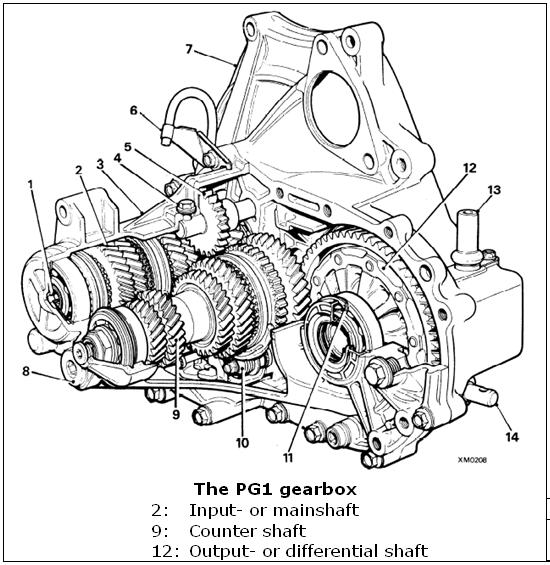
The Powertrain PG1 gearbox of Rover origin is renowned for its strength and to be easy to work on. It was fitted to the Lotus Elise but front and foremost to a lot of Rover cars.
The workshop manual for the PG1 gearbox can be downloaded from the web thanks to rover-coupe.com and should just be followed. This site is a good source of information of the various versions of the PG1 gearbox. You can also find good threads on other Lotus/MG/Rover forums with pictures to pick from. However I found that a good describtion of the procedure of shimming the gearbox bearings was missing in the workshop manual and in the forum threads. After having been through the procedure I will pass on my experiences as a supplement to the above sources and hope it will of help to others in the process.
Input shaft
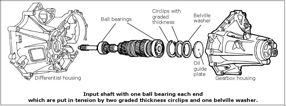
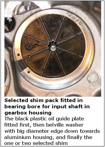
The input shaft is supported by two single-track ball bearings one at each end. The bearing in the clutch/differential house end is press fit in the bore. The bearing at the other end of the input shaft ie. in the gearbox casing is push fit in the bore. One or two shims are fitted in the bore behind this bearing. The shims look like circlips but have graded thickness. Behind these circlips is placed a belville washer. The idea is to put the bearings under tension by compressing the belville washer.
The aim when adjusting the input shaft is to choose the graded circlip thichness so that the belville washer is 0,17 mm from being fully compressed thereby putting the ball bearings at each end in tension.
Measuring input shaft end play
Start by assembling the input shaft with gear wheels, distance collars, syncro hubs etc. according to the gearbox manual. Wrap some pvc-tape around the clutch splines on the shaft to protect the oil seal from damage. Fit a new oil seal and bearing for the input shaft in the differential housing. When removing the old bearing it is good practise to heat up the housing locally from the outside to around 80°C and then lightly knock the housing onto a piece of wooden board. The bearing will then drop out easily and without any damage. When fitting the new bearing also heat up the house and the new bearing will drop in easily. The heating should be done with an electric heat gun – the common ones for paint stripping are just fine. Check the temperature with one of the infraread laser pointer thermometers that can be bought in most tool shops for sensible money.
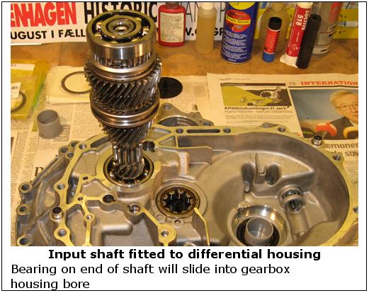
Place the differential housing on your work bench with the engine flange down. Drop in the assembled input shaft into its bearing in the differential housing. Be careful not to damage the oil seal. Fit the ball bearing on the end of the input shaft pointing upwards.
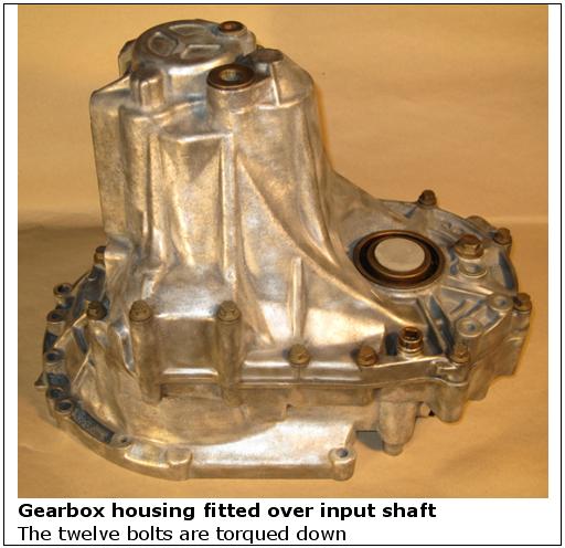
Remove the graded circlips, belville washer and oil guide plate from the bearing bore in the gearbox housing and clean the bore carefully. Clean the flange faces from old sealant. Fit the two location dovels in the bores in the flange. Fit the gearbox housing over the input shaft bearing, assure the diff and the gearbox housing flanges meet without tension, fit the 12 flange bolts and torque them down.
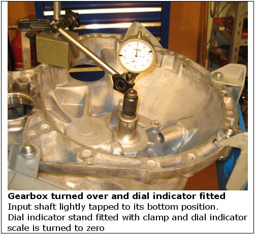
Now turn over the gearbox so the input shaft points up. When turning the gearbox over you will hear the input shaft moving because of the slack from the missing shim pack. Ligtly tap the end of the input shaft to assure the bearing at the other end is fully seated in its bore.
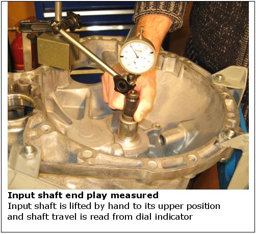
Place a dial indicator on the end of the input shaft. With your fingers lift the input shaft up and move it down again and keep track of the size of its movement on the indicator. Now you have measured the shaft end play without shim pack. In my case it was 1,68 mm.
Calculation of shim thickness
Take the belville washer and measure the material thickness. In my case it was 0,83 mm. So if the belville washer was completely compressed flat it would take up 0,83 mm.
According to the specifications the belville washer should be allowed to retract 0,17 mm from the completely flat position. Therefore add 0,17 mm to the belville washer material thickness to find the distance the belville washer should be allowed to take up. In my case it summed up to 0,83 + 0,17 = 1,00 mm.
To find the required additional thickness of one or eventually two circlip shims you should subtract the room occupied by the belville washer from the measured input shaft end play. In my case it was 1,68 ÷ 1,00 = 0,68 mm. The circlip shims can be bought in thickness steps of 0,05 mm from 0,50 mm to 1,15 mm and the “released thickness” of the belville washer should be within 0,14 – 0,21 mm. The average is 0,17 mm and this is what you aim at in the calculation. In my case I therefore could fit just one circlip shim of 0,70 mm thickness on top of the belville washer.
Shim availability
The thickness-graded circlip shims are a no longer easy to get hold of. In my case I fitted a new end bearing that was 1 mm wider than the bearing it substituted. So I could remove one of the two shims in the existing shim pack which consisted of a 0,95 mm and a 0,85 mm shim. So the 0,95 mm shim went out. The remaining 0,85 mm shim should be substituted by a 0,70 mm shim. I ordered a 0,70 mm shim from Rimmer Bros but it was backordered and arrived about 3 weeks later. By friendly contacts in UK a shim was sourced from a local dealer and it arrived within a couple of weeks. But if you are in a hurry as I were you can ask a machine shop with a surface grinder equipped with magnetic table to grind down an existing shim. In my case the 0,85 mm shim was ground down to 0,7 mm. Ultimately a shim can be lasercut out of shim sheet steel if no other ways can be found.
Counter shaft
The counter shaft runs in a roller bearing in the differential housing and in a double track ball bearing in the gearbox housing. The gearbox end ball bearing picks up all axial forces alone. Thanks to the layout the counter shaft bearings don’t need adjusting.
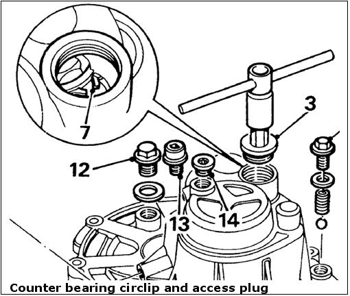
The gearbox end ball bearing is fastened to the counter shaft by a big nut with a left hand thread. The outer ring of this bearing is held in position in the gearbox house bore by a circlip which at disassembly has to be expanded through an access plug to release the bearing outer ring when lifting off the gearbox house.
Differential bearings
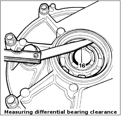
The differential or output shaft is supported by two ball bearings which as mentioned earlier should be substituted by the steel cage type bearings as the original plastic cage type is reported to sometimes crack under high loads. The bearings are shimmed at the gearbox casing end only and with a graded thickness circlip. The procedure is well described in the manual. You drop in the differential with its bearings in the differential housing, put on the gearbox housing and torque down the 12 bolts. Lightly drive the differential output shaft towards the circlip to seat it properly. Lightly drive the shaft in the other direction towards gearbox casing. From the outside you can now measure the slack between the outer ring and the circlip with a feeler gauge.
The clearance should be “up to 0,15 mm”. The circlip can be removed from the outside through the oil seal bore if the clearance is not met. The circlips are available in graded thickness.
So now we are through the task of checking and adjusting the bearings of the three shafts in the PG1 gearbox. I hope this description can be of some help to others tackling the task of rebuilding a PG1 gearbox.
