Uncategorised files
Jump to navigation
Jump to search
Showing below up to 50 results in range #1 to #50.
View (previous 50 | next 50) (20 | 50 | 100 | 250 | 500)
- 000004.jpg 320 × 160; 5 KB
- 0011.JPG 448 × 336; 24 KB
- 001369.jpg 320 × 128; 4 KB
- 01accesspanel.jpg 1,408 × 1,056; 143 KB
- 01resistorchange.jpg 500 × 375; 58 KB
- 02resistorchange.jpg 500 × 375; 40 KB
- 03resistorchange.jpg 500 × 667; 84 KB
- 04052009082.jpg 1,024 × 768; 102 KB
- 04resistorchange.jpg 1,408 × 1,056; 132 KB
- 0502.JPG 2,048 × 1,536; 694 KB
- 05resistorchange.jpg 500 × 375; 61 KB
- 06resistorchange.jpg 500 × 667; 92 KB
- 07resistorchange.jpg 500 × 375; 42 KB
- 10. Lower Ball Joint Split From Hub Carrier.JPG 600 × 450; 46 KB
- 100000.JPG 640 × 474; 101 KB
- 1012-011-Braid-FR-S1-Felgensatz-Elise-Mk1-1.jpg 2,016 × 1,512; 841 KB
- 10 Remove Upper & Lower Ball Joint Nuts.JPG 600 × 450; 45 KB
- 11. Steering Wheel Set To Full Lock.JPG 600 × 450; 45 KB
- 111F1-t.jpg 333 × 145; 5 KB
- 111RSE2-t.jpg 333 × 145; 5 KB
- 111R and S2 Exige ITG Maxogen.jpg 650 × 291; 51 KB
- 111R and S2 Exige ITG Panel Filter.gif 400 × 400; 52 KB
- 111S2bularfullperformancesystem.jpg 500 × 405; 91 KB
- 111Sprotypelargesilencertwin3inchdtm.jpg 600 × 265; 136 KB
- 111rforge.jpg 400 × 394; 24 KB
- 111rserv2.JPG 790 × 799; 103 KB
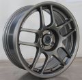
- 111rwheel.jpg 181 × 258; 9 KB
- 11 Remove Both Ball Joints.JPG 600 × 450; 46 KB
- 12. Ball Joint Removal Tool Assembled.JPG 600 × 450; 48 KB
- 12 Hub Carrier Removed.JPG 600 × 450; 50 KB
- 12spoke.jpg 640 × 467; 52 KB
- 13. Removing Ball Joint.JPG 600 × 450; 46 KB
- 13 The spring Clips Usually Come Off the Balljoint Rubber.JPG 650 × 488; 42 KB
- 14. Ball Joint Removed.JPG 600 × 450; 48 KB
- 14a Remove the Upper Wishbone 1.JPG 600 × 450; 46 KB
- 14b Remove The Upper Wishbone 2.JPG 600 × 450; 49 KB
- 15. Greasing New Ball Joint Rubber.JPG 600 × 450; 47 KB
- 154 0.jpg 200 × 109; 4 KB
- 155 0.jpg 200 × 126; 4 KB
- 15 x 6.5 TC5 Flow-Formed Gun metal matt-1.JPG 3,121 × 3,101; 521 KB
- 15a Upper Wishbone Removed 1.JPG 650 × 488; 40 KB
- 15b Upper Wishbone Removed 2.JPG 600 × 450; 43 KB
- 15c Upper Wishbone.JPG 600 × 450; 44 KB
- 16. Fitting New Ball Joint.JPG 580 × 435; 47 KB
- 16 x 8.0 TC5 Flow-Formed Mystic silver.JPG 3,121 × 3,074; 552 KB
- 16a Remove Lower Wishbone 1.JPG 650 × 488; 39 KB
- 16b Remove Lower Wishbone 2.JPG 650 × 488; 50 KB
- 16c Lower Wishbone.JPG 650 × 488; 39 KB
- 17. Ball Joint Assembly Tool.JPG 600 × 450; 44 KB
- 17 Both Wishbones Removed.JPG 650 × 488; 40 KB


