Difference between revisions of "Throttle Linkage"
Lithopsian (talk | contribs) (comment on rubbing) |
|||
| (4 intermediate revisions by 2 users not shown) | |||
| Line 6: | Line 6: | ||
<br style="clear:both" /> | <br style="clear:both" /> | ||
[[Image:Throttlelinkage3.jpg|thumb|150px|Step3|left]]The base plate was lifted away and positioned where I could work on it. I noticed that there has been a lot of scraping going on where the link has been rubbing on the base plate for the last 48,000 miles. | [[Image:Throttlelinkage3.jpg|thumb|150px|Step3|left]]The base plate was lifted away and positioned where I could work on it. I noticed that there has been a lot of scraping going on where the link has been rubbing on the base plate for the last 48,000 miles. | ||
| − | + | ''The black button in the middle of the throttle lever is a "slider button". It is meant to rub on the plate, that's the thin dark rubbed area. When the button wears down, the rest of the lever may start to rub, which is the wider rubbed area in your picture. The button can be replaced and will greatly improve the smoothness of the throttle movement in these cases. DeRoure says £1.03 factory order. Without a good button, there is extra strain on the pivot bushes and nylon washers and the whole lot will start to flex again more quickly than it should.'' | |
<br style="clear:both" /> | <br style="clear:both" /> | ||
[[Image:Throttlelinkage4.jpg|thumb|150px|Step4: I decided to disconnect the throttle cable side first so a Phillips screwdriver on one side and a 7mm socket on the other.|left]] | [[Image:Throttlelinkage4.jpg|thumb|150px|Step4: I decided to disconnect the throttle cable side first so a Phillips screwdriver on one side and a 7mm socket on the other.|left]] | ||
| Line 30: | Line 30: | ||
[[Image:Throttlelinkage7f.jpg|thumb|150px|left]]7e: The nut only needed to be nipped up otherwise I would have snapped the stud or crushed the bearing. | [[Image:Throttlelinkage7f.jpg|thumb|150px|left]]7e: The nut only needed to be nipped up otherwise I would have snapped the stud or crushed the bearing. | ||
| − | After nipping up the nut I checked to make sure the linkage moved freely. This is when I found that I needed two washers at the bottom, because the | + | After nipping up the nut I checked to make sure the linkage moved freely. This is when I found that I needed two washers at the bottom, because the linkage still rubbed on the base plate with only one washer. |
| − | I also checked to make sure the nut was tightened up correctly so the | + | I also checked to make sure the nut was tightened up correctly so the linkage moved freely but was not loose at the same time. |
<br style="clear:both" /> | <br style="clear:both" /> | ||
| Line 76: | Line 76: | ||
Now.. as you might notice, I've added a small M4 washer in the stack (standard M4 washer). I've done this to prevent any locking action between the thick nylon ring and the throttle linkage. | Now.. as you might notice, I've added a small M4 washer in the stack (standard M4 washer). I've done this to prevent any locking action between the thick nylon ring and the throttle linkage. | ||
It's not absolutely necessary (if it's moving, it's moving) but it gives just a little more freedom to move, so precautionary action..) | It's not absolutely necessary (if it's moving, it's moving) but it gives just a little more freedom to move, so precautionary action..) | ||
| + | |||
| + | |||
| + | |||
| + | [[Category:Interior]] | ||
| + | [[Category:Engine]] | ||
| + | [[Category:Air Induction]] | ||
Latest revision as of 17:01, 19 March 2020
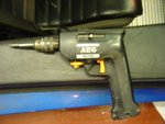
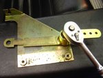
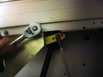
Step 1 Some of you may stumble here because the two screws holding the base plate on can be very tight and unless you are an Ironman which I am not you won't be able to apply enough torque with a normal screwdriver to get the screws undone. I used an AEG torque application device for this step. You can see me removing one of the screws with the AEG on the left hand side.
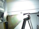
Step 2 - Yvo's instructions say you should remove the throttle return spring so the base plate can come out but I found that it was not necessary, so step 2 must only apply to left hand drive cars. You can see the throttle return spring on the right hand side of the photograph.
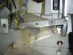
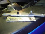
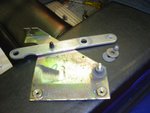
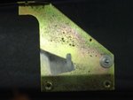
The base plate was lifted away and positioned where I could work on it. I noticed that there has been a lot of scraping going on where the link has been rubbing on the base plate for the last 48,000 miles.
The black button in the middle of the throttle lever is a "slider button". It is meant to rub on the plate, that's the thin dark rubbed area. When the button wears down, the rest of the lever may start to rub, which is the wider rubbed area in your picture. The button can be replaced and will greatly improve the smoothness of the throttle movement in these cases. DeRoure says £1.03 factory order. Without a good button, there is extra strain on the pivot bushes and nylon washers and the whole lot will start to flex again more quickly than it should.
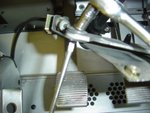
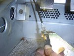
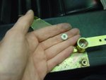
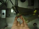
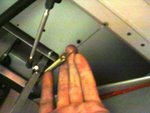
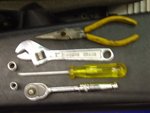
Step 5 - My smallest open ended spanner is 8mm, which was too big for the next step because the ball joint required a 6mm open ended spanner on the back side of the linkage.
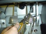
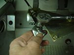
I used long nosed pliers to grasp the back of the ball joint and used an 7mm socket to undo the nut. It wasn't a problem because the nut was only nipped up.
See the photograph in step 8 showing the position of the pliers.
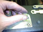
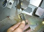
7e: The nut only needed to be nipped up otherwise I would have snapped the stud or crushed the bearing.
After nipping up the nut I checked to make sure the linkage moved freely. This is when I found that I needed two washers at the bottom, because the linkage still rubbed on the base plate with only one washer.
I also checked to make sure the nut was tightened up correctly so the linkage moved freely but was not loose at the same time.
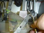
Step 8 - Then it was time to fit it all back together. Here is the photograph that shows the pliers clamping the ball joint and nipping up the nylock nut. This is what I was referring to back in step 5.
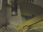
I originally used the middle hole for the standard throttle option as shown in this photograph, but I later changed my mind and moved it to the inner hole for the quick throttle option.
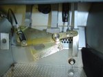
The photograph in step 9f shows the linkage connected in the inner position for the quick throttle option.
9f: All ready for the base plate to be bolted back on.
This photograph has been updated since I originally fitted the linkage.
I have now connected the throttle linkage to the inner hole and it is set up to give the quick throttle option.
For the standard setting (middle hole) I did not have to make any changes to either the throttle stop or at the throttle body end. See the photograph in step 8.
For quick throttle setting (inner hole) I had to adjust the throttle stop by approximately 10mm, but I found that I did not need to make any adjustments at the throttle body end.
I checked to make sure that everything moved freely and started the car up. I noticed an instant improvement in the smoothness of the throttle. It's one of the best and cheapest modifications that I have done to my car.
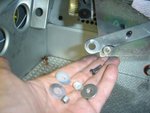
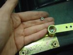
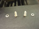
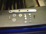
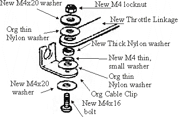
Correct nut:washers:bolt assembly
Now.. as you might notice, I've added a small M4 washer in the stack (standard M4 washer). I've done this to prevent any locking action between the thick nylon ring and the throttle linkage. It's not absolutely necessary (if it's moving, it's moving) but it gives just a little more freedom to move, so precautionary action..)
